
Phau Ntawv Qhia


Page 11
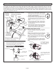
STEP 4 – ELECTRICAL – (Continued) – High Voltage and Field Control Wiring
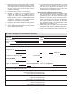
The following illustration provides an example of control wiring connections when using a standard thermostat.
Any excess high voltage field wiring should be trimmed and secured away from any low voltage field wiring. To facilitate a conduit, a cutout is
located in the bottom of the control panel. Connect conduit to the control panel using a proper conduit fitting.
ROUTING HIGH VOLTAGE, GROUND AND CONTROL WIRING
WIRE RUN LENGTH AWG# INSULATION TYPE
LESS THAN 100' (30 METERS) 18 TEMPERATURE RATING
MORE THAN 100' (30 METERS) 16 35ºC MINIMUM.
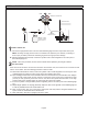
Install low voltage wiring from outdoor to indoor unit and from thermostat to indoor unit as illustrated.
HIGH VOLTAGE / GROUND WIRES
A - Run 24VAC control wires through hole with grommet.
B - Make 24VAC thermostat wire connections to CMC1.
NOTE - For proper voltages, select thermostat wire (control wires) gauge per
table below.
NOTE - Wire tie provides low voltage wire strain relief and maintains separation of field-installed low and high voltage circuits.
NOTE - Do not bundle any excess 24VAC control wires inside control panel.
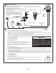
TYPICAL CONTROL WIRING
R
C
W1
Y1
O
G
R
C
W1
W2
W3
G
REVERSING VALVE
Thermostat
Indoor Unit
R
C
W1
Y1
O
Outdoor Unit
POWER
COMMON
1ST. STAGE AUX.
HEAT
INDOOR BLOWER
COMPRESSOR
(SOME CONNECTIONS MAY NOT APPLY. REFER
TO SPECIFIC THERMOSTAT AND INDOOR UNIT. )
POWER
COMMON
1ST. STAGE AUX.
HEAT
Low Voltage Wiring
R
C
W1
Y1
O
G
R
C
W1
W2
W3
G
Thermostat
Indoor Unit
Outdoor Unit
E
R
C
W1
Y1
O
1ST. STAGE AUX.
HEAT
EMER.
HEAT
RELAY
OUTDOOR
T'STAT
(SOME CONNECTIONS MAY NOT APPLY. REFER TO
SPECIFIC THERMOSTAT AND INDOOR UNIT. )
REVERSING VALVE
POWER
COMMON
1ST. STAGE AUX.
HEAT
INDOOR BLOWER
COMPRESSOR
POWER
COMMON
EMERGENCY
HEAT
Low Voltage Wiring (with Auxiliary Heat)
HIGH VOLTAGE
FIELD WIRING
LOW VOLTAGE
FIELD WIRING
FACTORY
WIRING
FIGURE 11
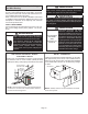
STEP 5 – UNIT START-UP
IMPORTANT
If unit is equipped with a crankcase heater, it should
be energized 24 hours before unit start-up to prevent
compressor damage as a result of slugging.
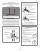
1 - Rotate fan to check for binding.
2 - Inspect all factory- and eld-installed wiring for
loose connections.
3 - After evacuation is complete, open the liquid line
and vapor line service valve stems to release the
refrigerant charge (contained in outdoor unit) into
the system.
4 - Replace the stem caps and tighten to the value
listed in table 2.
5 - Check voltage supply at the disconnect switch. The
voltage must be within the range listed on the unit’s
nameplate. If not, do not start the equipment until
you have consulted with the power company and
the voltage condition has been corrected.
6 - Connect manifold gauge set for testing and
charging.
7 - Set the thermostat for a cooling demand. Turn
on power to the indoor indoor unit and close the
outdoor unit disconnect switch to start the unit.
8 - Recheck voltage while the unit is running. Power
must be within range shown on the unit nameplate.
9 - Check system for sucient refrigerant using the
procedures outlined under Checking Refrigerant
Charge.
OPERATING MANIFOLD GAUGE SET AND SERVICE
VALVES
The liquid and vapor line service valves are used for re-
moving refrigerant, ushing, leak testing, evacuating,
checking charge and charging.
Each valve is equipped with a service port which has a
factory-installed valve stem. Figures 12 and 13 provide
information on how to access and operate both angle- and
ball-type service valves.