
Phau Ntawv Qhia

©2022 Lennox Industries Inc.
Dallas, Texas, USA
Page 1
THIS MANUAL MUST BE LEFT WITH THE
HOMEOWNER FOR FUTURE REFERENCE
WARNING
Improper installation, adjustment, alteration, service
or maintenance can cause property damage, personal
injury or loss of life. Installation and service must be
performed by a licensed professional HVAC installer or
equivalent, or service agency.
WARNING
To prevent serious injury or death:
1. Lock-out/tag-out before performing maintenance.
2. If system power is required (e.g., smoke detector
maintenance), disable power to blower, remove fan
belt where applicable, and ensure all controllers
and thermostats are set to the “OFF” position before
performing maintenance.
3. Always keep hands, hair, clothing, jewelry, tools, etc.
away from moving parts.
INSTALLATION
INSTRUCTIONS
HEAT PUMP
508263-01
6/2022
Merit
®
Series ML17XP1 Units
General
This ML17XP1 outdoor heat pump with all-aluminum coil
is designed for use with HFC-410A refrigerant only. This
unit must be installed with an approved indoor air handler
or coil. For AHRI Certied system match-ups and expand-
ed ratings, visit www.LennoxPros.com. These instructions
are intended as a general guide and do not supersede
local codes in any way. Consult authorities having jurisdic-
tion before installation.
NOTICE!
Charging information is given on the charging
procedure sticker on the unit access panel. For
more in-depth information, consult the Installation
and Service Procedures manual, available on
LennoxPros.com or through the Technical Support
department at 800-453-6669.
CAUTION
As with any mechanical equipment, contact with sharp
sheet metal edges can result in personal injury. Take
care while handling this equipment and wear gloves and
protective clothing.
IMPORTANT: Special procedures are required for clean-
ing the all-aluminum coil in this unit. See page 15 in this
instruction for information.
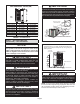
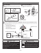
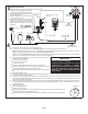
NOTES -
Service clearance of 30 in. (762 mm) must be maintained on one of
the sides adjacent to the control box.
Clearance to one of the other three sides must be 36 in. (914 mm).
Clearance to one of the remaining two sides may be 12 in. (305
mm) and the final side may be 6 in. (152 mm).
A clearance of 24 in. must be maintained between two units.
48 in. (1219 mm) clearance required on top of unit.
See
NOTES
See NOTES
See NOTES
See
NOTES
CONTROL
BOX
STEP 1 – SETTING THE UNIT – Clearances