PRODUCT LITERATURE Lennox Industries Inc. Dallas, Texas INSTALLATION INSTRUCTIONS GWB9-050IH-2 GWB9-075IH-2 GWB9-100IH-2 GAS-FIRED, DIRECT VENT, CONDENSING, HOT WATER BOILER RETAIN THESE INSTRUCTIONS FOR FUTURE REFERENCE These instructions must be affixed on or adjacent to the boiler. ! WARNING Improper installation, adjustment, alteration, service, or maintenance could result in death or serious injury. Refer to this manual for assistance.
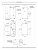
DIMENSIONS Figure 1 - Boiler Dimensions 2
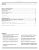
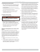
INTRODUCTION Dimensions.................................................................................................................... 2 Introduction................................................................................................................... 3 Important Safety Information........................................................................................... 4 Boiler Ratings & Capacities ..........................................................................................
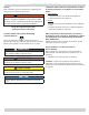
IMPORTANT SAFETY INFORMATION General Boiler installation shall be completed by qualified agency. See glossary for additional information. Installation shall conform to requirements of authority having jurisdiction or in absence of such requirements: • United States ! WARNING • National Fuel Gas Code, ANSI Z223.1/NFPA 54. Fire, explosion, asphyxiation and electrical shock hazard. Improper installation could result in death or serious injury.
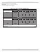
BOILER RATINGS & CAPACITIES Table 1 - SEA LEVEL RATINGS – NATURAL AND PROPANE GASES Model Input *(MBH) ++ Heating Capacity *(MBH) Net AHRI Rating *(MBH) Shipping Weight (lbs.) Flue Diameter 90-50 50 45 39 220 2” CPVC & PVC 90-75 75 68 59 220 2” CPVC & PVC 90-100** 100 90 78 220 2” CPVC & PVC * 1 MBH = 1,000 Btuh Btuh = British Thermal Units Per Hour ** 90-100 model is certified for natural gas only.
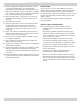
BOILERS FOR USE AT HIGH ALTITUDE - UNITED STATES INSTALLATIONS • Instructions on how to adjust gas manifold pressure settings see Figure 27 and Figure 28, Page 44. • Boilers (with exception of 90-75 propane (LP) product) are factory equipped for operation at altitudes ranging from 0-10,000 feet above sea level. Note 90-75 propane (LP) applications for 5,000 - 10,000 feet above sea level require orifice change as well as gas manifold pressure adjustment based upon calorific (Btu) value of supply gas.
BOILERS FOR USE AT HIGH ALTITUDE - UNITED STATES INSTALLATIONS Model 90-75 propane (LP) units only at altitudes above 5,000 ft., install 90-75 High Altitude Orifice Kit #550002629*. For all other altitudes use sea level orifice Table 3 - 90 - 50/75 SERIES 2 PROPANE GAS MODEL 90-50 Stock Factory Btu Value of Propane Gas++ Settings 2300 2350 2400 2450 0-5,000 5,000-10,000 2500 Altitude in Ft. Normal Input (MBH) 50 – – – – – Manifold Pressure In W.C. 2.5 3 3 2.5 2.5 2.
BEFORE INSTALLING THE BOILER 1. Boiler is equipped for residential installations. If used 2. 3. 4. 5. 6. 7. 8. 9. 10. Boiler Sizing for commercial applications, any additional code requirements must be adhered to for installation. This may require additional controls including but not limited to a low water cut off, a manual reset high temperature limit, and wiring and/or piping modifications. Before servicing boiler - allow boiler to cool.
BOILER INSTALLATION Locating The Boiler 1. Place crated boiler as close to selected location as • When vent pipe is exposed to temperatures below freezing, such as when it passes through an unheated space or when chimney is used as a raceway, vent pipe must be insulated with 1/2” Armaflex or equivalent. In extreme cold climate areas, use ¾” Armaflex or equivalent. possible and un-crate boiler. Boiler may be moved into position with appliance dolly or 2 wheel hand truck.
BOILER INSTALLATION 3. In-so-far as is practical, close all building doors and Condensate Drain Requirements • Pitch condensate drain line down to floor drain at minimum of ¼” per foot. External condensate pump (not furnished) may be used if floor drain is not available. • Condensate pump must be designed for flue gas condensate application. • Condensate trap provided with boiler, an additional trap is not required and should not be used.
NEAR BOILER PIPING Clean the System First Supply And Return Lines Before connecting boiler to heating system, clean and flush system thoroughly. Verify system is free of sediment, flux and any residual boiler water additives. • Boiler is set up to receive 1 ¼” NPT supply and return piping from top access. Systems having antifreeze not recommended must be completely flushed to insure no old antifreeze remains.
NEAR BOILER PIPING Figure 2 - Single Zone Boiler Piping 12
NEAR BOILER PIPING Multi-Zone Systems Multi-zone systems with two zones are typically piped as shown in figures 3 or 4. Multi-zone systems with more than two zones are likely to have small zones with very low heat and flow requirements compared to full heating capacity of the boiler. This can result in very low flow in the boiler if only one small zone is calling for heat.
NEAR BOILER PIPING Figure 4 - Two Zone Boiler Piping With Circulators 14
NEAR BOILER PIPING Figure 5 - Primary/Secondary Piping And Wiring With Circulators And Domestic Hot Water 15
NEAR BOILER PIPING Figure 6 - Piping and Wiring Primary/Secondary Multi Zone System Piping With Zone Valves And Domestic Hot Water (With Zone Valve) 16
NEAR BOILER PIPING Figure 7 - Piping And Wiring Primary/Secondary Piping With Zone Valves And Domestic Hot Water (With Circulator) 17
NEAR BOILER PIPING ! WARNING Figure 8 - Relief Valve Boiler Piping Burn and scald hazard. Safety relief valve could discharge steam or hot water during operation. Install discharge piping per these instructions. RELIEF VALVE Safety Relief Valve Installation of safety relief valve shall conform to ANSI/ ASME Boiler and Pressure Vessel Code, Section IV. • Install furnished safety relief valve using 3/4” x 4½” pipe provided with boiler. See Figure 8.
NEAR BOILER PIPING Figure 9 - Diaphragm Type Expansion Tank Piping 19
NEAR BOILER PIPING Figure 10 - Conventional (Closed Type) Expansion Tank Piping 20
NEAR BOILER PIPING Condensate Drain Piping Filling Condensate Trap With Water Boiler is factory equipped with a condensate trap. An additional trap is not required and should NOT be used. 1. Provide ½” PVC condensate drain and fittings. Condensate drain to be pitched down to floor drain at a minimum of ¼” per foot. 2. Install ½” PVC tee to overflow fitting as shown in Figure 11. 3.
COMBUSTION AIR AND VENT PIPE Connections And Termination Provisions for combustion and ventilation air must be in accordance with section, Air For Combustion and Ventilation, of the National Fuel Gas Code,ANSI 2223.1/ NFPA54, or Sections 8.2, 8.3 or 8.4 of National Gas and Propane Installation Code, CAN/CGA-B 149.1, or applicable provisions of the local building code. Boilers require dedicated direct vent system. All air for combustion is taken directly from outdoors through combustion air intake pipe.
COMBUSTION AIR AND VENT PIPE Table 5 - Combustion Air And Vent Piping Lengths - Total Equivalent Length BOILER SIZE 2” PIPE MINIMUM VENTING 2” PIPE MAXIMUM VENTING 3” PIPE MINIMUM VENTING 3” PIPE MAXIMUM VENTING 100 2 FEET 21 FEET 15 FEET 92 FEET 75 & 50 2 FEET 26 FEET 20 FEET 112 FEET • Under certain conditions, flue gas will condense, forming moisture, and may be corrosive. Take steps to prevent building materials at vent from being damaged by exhaust of flue gas.
COMBUSTION AIR AND VENT PIPE Figure 12 - Roof Vent / Intake Terminations VENT AIR INTAKE 24
COMBUSTION AIR AND VENT PIPE Figure 13 - Side Wall Vent / Intake terminations - Less Than 12” Clearance Above Grade Less Than 12” Clearance Figure 14 - Side Wall Vent/Intake Terminations - 12” Or More Clearance Above Grade 12” Or More Clearance 25
COMBUSTION AIR AND VENT PIPE Figure 17 - Concentric Vent Roof Installation Figure 15 - Concentric Vent Terminations 1" (2.54cm) Maximum NOTE: SUPPORT MUST BE FIELD INSTALLED TO SECURE TERMINATION KIT TO STRUCTURE. VENT D COMBUSTION AIR A Vent Combustion Air 1" (2.54cm) Maximum * See Note Below C Overhang A 12" (30cm) Minimum B 36"(0.
COMBUSTION AIR AND VENT PIPE Figure 18 - Combustion Air and Vent Piping - Boiler Connections 2” (50.8mm) DIAMETER VENT AND COMBUSTION AIR INTAKE PIPING - 21 feet maximum total equivalent length for 90-100 models -26 feet maximum total equivalent length for 90-50 and -90-75 models - 2 feet minimum total equivalent length for all models TRANSITION FITTING 2” (50.8mm) ⊘ to 3” (76.2mm) ⊘ IN VERTICAL RUN 3” (76.
GAS SUPPLY PIPING ! CAUTION ! WHAT TO DO IF YOU SMELL GAS • Do not try to light any appliance. Fire Hazard. Do not use matches, candles, open flames, or other methods providing ignition source. Failure to comply will result in death or serious injury. • Do not touch any electrical switch; do not use any phone in your building. • Immediately call your gas supplier from a neighbor’s phone. Follow gas supplier’s instructions. • If you cannot reach your gas supplier, call the fire department.
GAS SUPPLY PIPING Table 7 – Gas Pipe Sizes NATURAL GAS Pipe Capacity - BTU Per Hour Input Includes Fittings Length of Pipe - Ft. 1/2” 3/4” 1” 1 1/4” 20 92,000 190,000 350,000 625,000 40 63,000 130,000 245,000 445,000 60 50,000 105,000 195,000 365,000 PROPANE GAS Pipe Capacity - BTU Per Hour Input Includes Fittings Length of Pipe - Ft.
ELECTRICAL WIRING Connect Circulator Pump Wiring ! WARNING See Figure 20, Page 31 for circulator pump field wiring connections. Supplied 5 foot wiring harness with flexible metal conduit for connection from circulator pump to junction box. If two 120 Volt circulator wire terminals inside junction box are not used, leave two wire nuts to prevent short circuit. Electrical shock hazard. Turn OFF electrical power supply at service panel before making electrical connections.
ELECTRICAL WIRING Figure 20 - Wiring Schematic NOTICE If any of original wire as supplied with this appliance must be replaced, it must be replaced with type 105°C Thermoplastic wire or its equivalent 31
ELECTRICAL WIRING Figure 21 - Ladder Wiring Diagram 32
ELECTRICAL WIRING Figure 22 - Suggested Wiring Schematic for Domestic Hot Water Priority Two Zone System with Circulators Using Argo AR822II Pump Relay 33
ELECTRICAL WIRING Figure 23 - Ladder Diagram for Figure 22 34
CONTROLS AND ACCESSORIES • Boiler temperature is cooling at a rate greater than 5°F/minute while circulator is running. This section provides a brief description of the key controls and accessories found in this boiler. See Figure 26, Page 41 for detailed sequence of operation. See the Repair Parts Manual for locations of all control components and accessories described. 4.
CONTROLS AND ACCESSORIES Casting Temperature Safety Switch Drain Valve In event of lack of or loss of water in boiler, Casting Temperature Safety Switch (300 °F setpoint) installed on top of the aluminum boiler section shuts off boiler by shutting off power to Integrated Boiler Control (IBC). This fault requires manual reset of casting temperature safety switch to restart the boiler. Verify that boiler is properly filled with water before resetting this switch.
START UP Water Quality, Water Treatment and Freeze Protection - see Appendix A Filling Boiler With Water And Purging Air For Systems With Diaphragm Type Expansion Tanks Refer to the appropriate diagrams,“Near Boiler Piping” on page 11 for more information. 1. Close all zone service valves on the supply and return piping. Open the feed valve and fill boiler with water. Make sure air vent is open.
OPERATING INSTRUCTIONS ! WARNING ! CAUTION If you do not follow these instructions exactly, a fire or explosion may result causing property damage, personal injury or loss of life. • This appliance is equipped with an ignition device which automatically lights burner. Do NOT try to light this burner by hand. WHAT TO DO IF YOU SMELL GAS • Do not try to light any appliance. • Do not touch any electrical switch; do not use any phone in your building.
S9381A INTEGRATED BOILER CONTROL OPERATION AND ADJUSTMENTS S9381A control has a number of user adjustable parameters as shown in Table 8. Table 8 - User Parameters Adjusting Settings To discourage unauthorized changing of settings, a procedure to enter the adjustment mode is required. To enter the adjustment mode, press the UP, DOWN, and I buttons simultaneously for three seconds. Press and release the I button until the parameter requiring adjustment is displayed.
S9381A INTEGRATED BOILER CONTROL OPERATION AND ADJUSTMENTS Table 9 - State Code Definitions 40
S9381A INTEGRATED BOILER CONTROL OPERATION AND ADJUSTMENTS Figure 26 - Sequence of Operation 41
CHECK OUT PROCEDURE AND ADJUSTMENT Verify Proper Sequence Of Operation Test Other Safety Controls Place boiler into operation and observe operation through several cycles. Follow remaining steps in this section to insure boiler is operating correctly. If boiler is equipped with low water cut off, manual reset high limit, or additional safety controls, test for operation as outlined by control manufacturer. Burner should be operating and should go off when controls are tested.
CHECK OUT PROCEDURE AND ADJUSTMENT Set Thermostat To Desired Room Temperature F. After adjusting input rate, turn boiler off, remove manometer or pressure gauge, reinstall ⅛” plug on gas valve. Turn boiler on. G. Boiler should typically operate between: Observe several operating cycles to verify proper operation. Review All Instructions • 8.5% -10.0% CO2 on Natural Gas • 9.5% -11.0% CO2 on Propane Gas Under all conditions CO level should not exceed 100 ppm. 9.
CHECK OUT PROCEDURE AND ADJUSTMENT Figure 27 - Manifold Pressure Measurement Detail Following steps and diagram indicate location of the connection points required to measure manifold pressure. Manifold pressure may be measured using a U-Tube Manometer or Differential Pressure Gauge. Diagram shows connection of both measuring devices. Only ONE DEVICE IS REQUIRED to measure manifold pressure. Remove plug.
MAINTENANCE AND CLEANING 2. Check boiler area is free from combustible materials, Maintenance As Outlined Below Can Be Performed By Owner Unless Otherwise Noted. gasoline, and other flammable vapors and liquids. 3. Circulator pump and blower motor furnished with boiler are permanently lubricated from factory and require no further lubrication. Additional or non-factory supplied pumps and/or motors should be lubricated according to the pump and/or motor manufacturer’s instruction.
MAINTENANCE AND CLEANING Annual Examination And Cleaning Of Boiler Components ! DANGER Before servicing, turn off electrical power to boiler at service switch. Close manual gas valve to turn gas supply OFF to boiler. Failure to comply will result in death or serious injury. NOTICE Have qualified service agency perform the following service procedures. Boiler owner should not attempt these procedures. 1. Before Servicing, turn off electrical power to boiler at service switch.
TROUBLESHOOTING ! WARNING 2. Troubleshooting tools: A. Voltmeter to check 120 vac and 24 vac B. Continuity tester. C. Inclined manometer or pressure gauge with 0-3.0” Range (0.01” Scale) for measuring suction pressures at pressure switch. D. U-tube manometer or differential pressure gauge with 0-14” range (0.1” Scale) for measuring inlet and manifold gas pressures. Fire, explosion or shock hazard. Do not attempt to modify the physical or electrical characteristics of this boiler in any way.
TROUBLESHOOTING Table 10 - Error Codes 48
DIFFERENTIAL AIR PRESSURE SWITCH CHECK • Following steps and diagram indicate locations of connection points required to check differential air pressure. • Differential air pressure switch is safety device which prevents boiler from firing if there is air intake, boiler heat exchanger or vent blockage. BOILER STATUS DIFFERENTIAL PRESSURE (W.C.) PRESSURE SWITCH CONNECTS Not Running 0” Normally Open Setpoint 1.00” for Model-100 1.60” for Model-75 2.
APPENDIX A - WATER QUALITY, WATER TREATMENT AND FREEZE PROTECTION Aluminum Series High Efficiency Gas-Fired Boiler DIELECTRIC ISOLATION & ANTIFREEZE PROTECTION ADDENDUM ! WARNING Follow these instructions to prevent damage to boiler’s heat exchanger caused by inadequate dielectric isolation, incorrect water treatment or antifreeze application. Failure to comply could result in death or serious injury.
System and Operating Precautions Applies to ALL Aluminum High Efficiency Gas-Fired Water Boilers Clean System First Eliminate System Leaks BEFORE connecting boiler to heating system, clean and flush system thoroughly. Verify system is free of sediment, flux and any residual boiler water additives. Continuous addition of make-up water will constantly add oxygen to system. Eliminate all system leaks. All system leaks must be repaired immediately.
System and Operating Precautions Applies to ALL Aluminum High Efficiency Gas-Fired Water Boilers General Guidelines When Using Antifreeze • Use only antifreeze products recommended for use with aluminum boilers, as listed in this addendum. See Table 11. • Continuous addition of make-up water will dilute power of antifreeze and change buffers ability to maintain pH. • Flush old antifreeze from system. Flush boiler and system separately. • Do not use antifreeze unless required.
System and Operating Precautions Applies to ALL Aluminum High Efficiency Gas-Fired Water Boilers Table 11 - Antifreeze Products Compatible Aluminum Antifreeze & Inhibitor Suppliers Noburst AL Antifreeze Noble Company P. O. Box 350 Grand Haven, MI 49417 www.noblecompany.com Tel: 800-878-5788 Fax: 231-799-8850 Rhogard Antifreeze & Pro-Tek 922 Inhibitor* Rhomar Water Management, Inc. P. O. Box 229 Springfield, MO 65801 www.rhomarwater.
INSTALLATION AND CHECK-OUT CERTIFICATE INSTALLATION AND CHECK-OUT CERTIFICATE Boiler Model Serial # Date Installed___________ Measured BTU/HR input____________ Installation instructions have been followed Checkout procedure and adjustments performed Maintenance and Service issues reviewed with owner/ maintenance person Installation booklet affixed on or adjacent to boiler Installer (Company) Address Phone Installer’s Name Signature 54
NOTES 55
PRODUCT LITERATURE Lennox Industries Inc. Dallas, Texas Manufactured by: ECR International, Inc. 2201 Dwyer Avenue, Utica NY 13501 web site: www.ecrinternational.