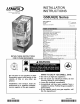
,1_2006 Lennox industries INSTALLATION INSTRUCTIONS Inc. Dallas, Texas, USA G50UH(X) Series GAS FURNACE 505,254M 8/2006 Supersedes 504,957M _ Technical .L_._L Publications Lithe U.S.A. Unit Dimensions ................................ G50UH(X) Parts Arrangement .................... G50UH(X) Gas Furnace .......................... Shipping and Packing List ........................ Safety Information ............................... General ........................................
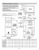
1 NOTE - 60C and 60D size units that require air volumes over 1800 cfm (850 L/s) must have one of the following: 1. Single side return air with transition, to accommodate 20 x 25 x 1 in. (508 x 635 x 25 mm) air filter. Required to maintain proper air velocity across the filter. 2. Single side return air with optional RAB Return Air Base 3. Bottom return air. 4. Return air from both sides. 5. Bottom and one side return air. See Blower Performance Tables for additional information.
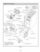
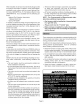
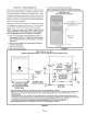
Air Deflector G50UH-48C-135, G50UH-60C-110 & G50UH-60D-155 UnitsOnly FlueBoxGasket HeatExchanger Gasket FlueCollectorBox FlueTransition % Combustion Air Orifice Combustion Air Pressure Switch Air Inducer Limit Shield Flame Sensor _ Flame Rollout Switches* Flame Rollout Bracket Primary Limit Gas Valve NOx Insert (NO x Units Only) \ Gas Orifices Ignitor Bracket Ig'_itor Secondary Limit Burner Bottom Shield Control Transformer _ _'_ SureLight ¢ Control Board _'_ "135 and 155 kBtuh units only -F
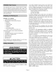
TheG50UH(X) gasfurnaceis shippedreadyforinstallationintheupfiowor horizontalposition(leftor right).The furnaceisshippedwiththebottompanelinplace.Thebottompanelmustberemovediftheunitistobeinstalledina horizontal application. Thepanelmayalsoberemovedin upfiowapplications. In the USA, installation of gas furnaces must conform with local building codes. In the absence of local codes, units must be installed according to the current National Fuel Gas Code (ANSI-Z223.1/NFPA 54).
Wheninstalled, thisfurnacemustbeelectrically grounded according tolocalcodes.Inaddition,intheUnitedStates, installationmustconformwiththecurrentNationalElectricCode,ANSI/NFPA No.70.TheNationalElectricCode (ANSI/NFPA No.70) is availablefromthe followingaddress: NationalFireProtection Association 1 BatteryMarchPark Quincy,MA02269 InCanada,allelectricalwiringandgrounding fortheunit mustbeinstalled according tothecurrentregulations ofthe CanadianElectricalCodePartI (CSAStandardC22.1) and/orlocalcodes.
Inthepast,therewasnoproblem inbringinginsufficient outdoorairforcombustion. Infiltration provided alltheairthat wasneeded.Intoday'shomes,tightconstruction practices makeit necessary to bringin airfromoutsideforcombustion.Takeintoaccountthatexhaustfans,appliance vents, chimneys, andfireplaces forceadditional airthatcouldbe usedforcombustion outofthehouse.
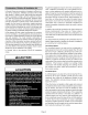
Air from Outside EQUIPMENT IN CONFINED SPACE ALL AIR FROM INSIDE CHIMNEY If air from outside is brought in for combustion and ventilation, the confined space must have two permanent open- VENT ings. One opening shall be within 12 inches (305 mm) of the top of the enclosure and one opening within 12 inches (305 mm) of the bottom.
EQUIPMENT IN CONFINED SPACE ALL AIR FROM OUTSIDE (All Air Through Ventilated Attic) CHIMNEY OR GAS VENT_ VENTILATION LOUVERS (Each end of attic) FURNACE INLET AIR (Ends 12 in. above bottom) HEATER NO TE- The inlet and outlet air openings shall each have a free area of at least one square inch (645 mm 2) per 4,000 Btu (1.17 kW) per hour of the total input rating of all equipment in the enclosure. _ JJ_ Select a location that allows for the required clearances that are listed on the unit nameplate.
Return Return Air -- Upflow air can be brought in through side of the furnace installed furnace on a platform is installed an airtight platform seal between to ensure safely. The furnace panel to facilitate Markings cabinet required tion, with bottom the bottom is equipped If the Side Return Air (with transition and filter) return, make of the furnace operates Refer to Engineering Handbook for additional information.
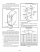
Removingthe Bottom Panel Leveling Bolt Installation Remove the two screws that secure the bottom cap to the furnace. Pivot the bottom cap down to release the bottom panel. Once the bottom panel has been removed, reinstall the bottom cap, See figure 9.
Thisfurnacemaybeinstalledineitheranatticora crawlspace.Eithersuspendthe furnacefromroof raftersor floorjoists,asshowninfigure12,orinstallthefurnaceon a platform,as shownin figure13.Theunitmustbesupportedat bothendsandbeneaththeblowerdecktopreventsagging. Horizontal Application Unit Installed on Platform NOTE - Line contact is permissible. See the unit nameplate for clearances.
Thisunitis notequippedwitha filteror rack.A field-providedhigh-velocity filteris requiredfortheunittooperate properly.Table1 listsrecommended filtersizes. Afiltermustbein placeanytimetheunitisoperating.
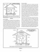
Usesheetmetalshearstoremove thecutoutfromtheside ofthecabinet.Usethetwoprovided sheetmetalscrewsto installthecutoutonthetopcaptocovertheoriginalflue outletopening.Seefigure15. TheG50UH(X) seriesunitsareclassified as fan-assisted CategoryI furnaceswhenverticallyventedaccordingto thelatesteditionof NationalFuelGasCode(NFPA54 / ANSI Z223.1 ) in the USA and the current standards of CSA B149 Natural Gas and Propane Installation Codes in Canada.
Common Venting Using Tile-Lined Interior Masonry Chimne ' and Combined Vent Connector J MINIMUM LENGTH = AS SHORT AS PRACTICAL. FOR MAXIMUM LENGTH SEE NOTE TO LEFT NOTE- Refer to provided venting tables for installations in the USA and the J venting tables in current CSA B149 for installations in Canada. INTERIOR TILE=LINED MASONRY CHIMNEY NOTE - the chimney must be properly sized per provided venting tables or lined with listed metal lining system.
5 - Theentirelengthofsinglewallmetalventconnector shallbe readilyaccessiblefor inspection,cleaning, andreplacement. 6 - Singleappliance ventingconfigurations withzerolaterallengths(tables3 and4) areassumedto haveno elbowsintheventsystem.Forallotherventconfigurations,theventsystemisassumedtohavetwo90° elbows.Foreachadditional 90°elbowor equivalent (for exampletwo45°elbowsequalone90°elbow)beyond two,the maximumcapacitylistedintheventingtable shouldbereduced by 10%(0.90x maximum listedcapacity).
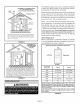
TABLE 3 Capacity Height H (feet) 6 8 10 15 20 30 Lateral L (feet) of Type B Double-Wall Vents with Type B Double-Wall Connectors Serving a Single Category I Appliance Vent and Connector 4 Inch 3 Inch Appliance MIN Diameter - D (inches) 5 Inch Input Rating in Thousands MAX MIN of Btu Per Hour MAX 6 Inch MIN MAX MIN MAX 0 0 78 0 152 0 251 0 375 2 13 51 18 97 27 157 32 232 4 21 49 30 94 39 153 50 227 6 25 46 36 91 47 149 59 223 0 0 84 0 165 0 276 0
TABLE 4 Capacity of Type B Double-Wall Vents with Single-Wall Metal Connectors Serving a Single Category I Appliance Vent and Connector Height H (feet) 6 8 10 15 20 30 Lateral L (feet) 3 Inch Diameter - D (inches) 4 Inch Appliance MIN 5 Inch Input Rating in Thousands MAX MIN MIN MAX 0 38 77 59 151 85 2 39 51 60 96 85 4 NR NR 74 92 6 NR NR 83 0 37 83 2 39 5 6 Inch of Btu Per Hour MAX MIN MAX 249 126 373 156 123 231 102 152 146 225 89 114 147 163 220
TABLE 5 Vent Connector Capacity Type B Double-Wall Vents with Type B Double-Wall Connectors Serving Two or More Category I Appliances Vent Height H (feet) 6 8 10 15 20 30 Vent and Connector Connector Rise R (feet) 3 Inch Diameter - D (inches) 4 Inch 5 Inch Appliance Input Rating in Thousands of Btu Per Hour MIN MAX MIN MAX MIN MAX 1 22 37 35 66 46 2 23 41 37 75 48 3 24 44 38 81 1 22 40 35 2 23 44 3 24 47 1 22 2 23 3 1 6 Inch MIN MAX 106 58 164 121 60 183
TABLE 7 Vent Connector Capacity Type B Double-Wall Vents with Single-Wall Metal Connectors Serving Two or More Category I Appliances Vent Height H (feet) 6 15 30 Vent and Connector Diameter - D (inches) Connector Rise R (feet) MIN MAX I NR NR NR NR NR 2 NR NR NR NR 3 NR NR NR NR 1 NR NR 79 2 NR NR 3 NR NR 1 47 2 3 3 Inch 4 Inch 5 Inch Appliance Input Rating in Thousands of Btu Per Hour MIN MAX MIN MAX 6 Inch MIN MAX NR NR NR NR NR 168 182 121 131 174 198
Resizethe commonventingsystemto the minimum ventpipesizedeterminedby usingthe appropriate tablesin appendixG. (Thesearein thecurrentstandardsoftheNationalFuelGasCodeANSIZ223.1in theUSA,andtheappropriate Category1 NaturalGas andPropaneappliances ventingsizingtablesin the currentstandardsof theCSAB149NaturalGasand PropaneInstallation CodesinCanada.) 3 - The gas piping must not run in or through air ducts, clothes chutes, gas vents or chimneys, dumb waiters, or elevator shafts.
Left Side Piping (Standard) MANUAL MAIN SHUT-OFF AUTOMATIC GAS VALVE (with manual shut-off valve) AUTOMATIC GAS VALVE (with manual VALVE (With 1/8 in. NPT Plugged Tap Shown) MANUAL VALVE (With 1/8 in.
INTERIOR MAKE-UP NOTE - The G5OUH(X) furnace contains electronic components that are polarity sensitive. Make sure that the furnace is wired correctly and is properly grounded. BOX INSTALLATION MAKE-UP Left side / _ BOX 7 - One line voltage "EAC" terminal is provided on the furnace control board. Any electronic air cleaner rated up to one amp can be connected to this terminal with the neutral leg of the circuit being connected to any of the "NEUTRAL" terminals.
TYPICAL G50UH(X) FIELD WIRING DIAGRAM {_V ACC S{O _IIIARYGAS K43 EC(_ (IF USEO) WARNINGELECTRIC SHOCK HAZARD,CAN CAUSE INJURY OR DEATH.UNIT MUST BE GROUNDED IN ACCORDANCE WITH NATIONAL AND LOCAL CODES, IMPORTANTTO PREVENT MOTOR BURNOUT,NEVER THAN ONE MOTOR LEAD TO ANY ONE PARK TERMINALS ARE UNUSED MOTOR LEADS PARK TERMINAL. C(_WBIJST I(_NAIR INN.ICERI_T_ {ALEImNATE} L I-_=======_ CONNECT MORE CONNECTION. UNPOWERED TERMINALS.
G5OUH(X) 120V ADO OR Schematic /_ SIS COMBUSTION AIR PROVING SWITCH SlO K43 ECON Wiring Diagram BLOWER SPEED CHART FACTORY CONNECTED SPEED PRIMARY GAS (IF USED) UNIT LIMIT COMBUSTION INDUCER AIR _ "-L£P./ MOTOR 6V I WHITE-RODGER9 /_ 0[] 0 0 0 0 L_DTS RED ........ 3 2¢A-070 36A-070 fELLOW RED .... BROWN 3 4 2 BROWN BROWN RED RED .... .... YELLOt YELLO_ 4 € {(RIGHT) I(RISHT) BROWN fELLOW fELLOW fELLOW RED RED RED RED .... .... .... ....
3 - Turn off all electrical power to the unit, 4 - This furnace is equipped with an ignition device which automatically lights the burners, Do not try to light the burners by hand, FOR YOUR SAFETY READ BEFORE LIGHTING 5 - Remove the upper access panel, AWARNING 6 - Honeywell VR8205 Gas Valve with ON/OFF Switch - Move gas valve switch to OFF, See figure 27. Honeywell VR8205 Gas Valve with Control Knob Turn knob on gas valve clockwise 41_ to OFF.
8- Honeywell VR8205 Gas Valve with ON/OFF Switch - Move gas valve switch to ON. See figure 27. Honeywell VR8205 Gas Valve with Control Knob Turn knob on gas valve counterclockwise _ to ON, Do not force.
ralgasatallaltitudesis3.5"w.c.Manifoldpressure for allunitsfueledbyL.R/propane gasat allaltitudesis 10.0"w,c.Seefigures27, 28and29forthelocationof themanifoldpressureadjustment screws, NOTE - In Canada, certification for installations at elevations over 4500 feet (1372 m) is the jurisdiction of local authorities. Manifold pressure for all units fueled by natural gas at all altitudes is 3.5" w,c, Manifold pressure for all units fueled by L,R/propane gas at all altitudes is 10,0" w,c, NOTE - A natural to L.
FlueAnd Chimney 1 - Checkfluepipe,chimneyandallconnections fortightnessandtomakesurethereisnoblockage, 2 - Checkunitforproperdraft, 3 - Ispressureswitchclosed?Obstructed fluewillcause unittoshutoffatpressure switch,Checkflueandoutlet forblockages. 4- Resetmanualflamerolloutswitcheson burnerbox cover.
4 - Removethecollectorboxlocatedbehindthecombustionairinducer.Becarefulwiththecollectorboxgasket.If thegasketis damaged,it mustbereplacedto preventleakage, 5 - Labelthewiresfromgasvalveandrolloutswitches, thendisconnect them. 6 - Disconnect gassupplypiping.Remove fourscrewssecuringthe burnermanifoldassemblytothevestibule panelandremovetheassemblyfromtheunit, NOx INSERTS (X models only) 11- Remove the cable from the heat exchanger. Use a vacuum cleaner to remove debris knocked loose during cleaning.
ThefollowingrepairpartsareavailablethroughLennoxdealers.
SURELIGHT ®CONTROL HEATING SEQUENCE OF OPERATION NORMAL HEATING MODE I POWER ON _' CONTROL SELF-CHECK ABNORMAL ] I GAS VALVE OFF. COMBUSTION I I I,_ _ ; NO | | v aYES _ I OKAY'_ " ,sPOLARITY REVERSED? _1 i- I I LED#1 AND LED#2 ALTERNATING FAST FLASH, SIGNAL NO HOLDS UNTIL UNIT IS| ._--I PROPERLY GROUNDi_I -_I I NO J_ • ISTHERE PROPER GROUND? /I / 1' I YESI I NO I MAIN POWER OFF) POLARITY REVERSED.
NORMAL HEATING MODE ABNORMAL 15-SECOND COMBUSTION INDUCERSW PREPURGE N T ATED BY CLOSED AIR PRESSURE TCH. YES I HEATING MODE 9 _ -_O YES_ . NO I YES_t INOI I--=-_l S VOLTAGE ABOVE 75 VOLTS? IGNITOR WARM-UP -- 20 SECONDS. YES _IIW GAS VALVE OPENS, IGNITOR ENERGIZED 4-SECOND UP TO TRIAL 4 SECONDS, FOR IGNITION. I ISTHERE A PROPER GROUND? ISIGNITOR INTACT AND CONNECTED?I_"I FOR INDOOR BLOWER OFF. HAS CONTROL FA LED TO SENSE FLAME FOR YES I FLAME STABILIZATION PERIOD.
SURELIGHT®CONTROL COOLING SEQUENCE OF OPERATION NORMALCOOLING I I MODE POWER ON ABNORMALCOOLING MODE l IGNITION CONTROL MA, NPOWER ON I GAS VALVE OFF, COMBUSTION AIR INDUCER OFR INDOOR BLOWER OFF WITH NORMAL DELAY. SIGNAL CIRCUIT BOARD FAILURE AT LED. INTERRUPT MAIN POWER TO RESET CONTROL, I CO.T O S O,A .OS ,OO. OK IS CONTROL OPERATING NORMALLY? Y sJ I ,sPOLARITY REVERSED? _ LED_IFAST FLASH LED_2 SLOW FLASH I / LED#1 AND LED#2 NO | ALTERNATING FAST I NO _ __ FLASH.
SURELIGHT ® CONTROL CONTINUOUS FAN SEQUENCE OF OPERATION I ! LED: SLOW FLASH RATE REMAINS UNCHANGED THROUGHOUT SEQUENCE. MANUAL FAN SELECTION I I MADE AT THERMOSTAT. CONTROL (G) ENERGIZES INDOOR BLOWER AT FAN SPEED. EAC TERM. IS ENERGIZED. / THERMOSTAT CALLS FOR HEAT (W). YEs NO THERMOSTAT I I--l't / HUM TERM. ENERGIZES WITH COMB. AIR INDUCER. I CALLS FOR COOLING. AFTER NORMAL DELAY. _YES INDOOR BLOWER SWITCHES TO COOL SPEED. I THERMOSTAT t AND HUM OPENS.
JobName JobNo. Date JobLocation City State Installer City State UnitModelNo. Technician SerialNo. Heating Section [] Electrical Connections Tight? Blower Motor H.P. SupplyVoltage BlowerMotorAmps [] Gas Piping Connections Tight & Leak-Tested? [] FuelType:NaturalGas? LP/Propane Gas? D [] FurnaceBtuInput Line Pressure Regulator Pressure w.c. _ Nat,: w.c.