GAS FURNACES G43UF MERIT® SERIES Up−Flow ENGINEERING DATA Bulletin No. 210394 August 2005 Supersedes December 2004 AFUE − up to 92.1% Input − 44,000 to 132,000 Btuh Nominal Add−on Cooling − 2 to 5 Tons MODEL NUMBER IDENTIFICATION G 43 UF − 24 B − 045 Unit Type G = Gas Furnace Series 43 = 90% Minimum AFUE Nominal Gas Heat Input 045 = 44,000 Btuh (12.9 kW) 070 = 66,000 Btuh (19.3 kW) 090 = 88,000 Btuh (25.8 kW) 110 = 110,000 Btuh (32.2 kW) 135 = 132,000 Btuh (38.
FEATURES CONTENTS Blower Data . . . . . . . . . . . . . . . . . . . . . . . . . . . . . . . . Pages 13−15 Dimensions . . . . . . . . . . . . . . . . . . . . . . . . . . . . . . . . . . Pages 9−12 Exhaust Pipe Venting Information . . . . . . . . . . . . . . . . . . . Page 7 Features and Options . . . . . . . . . . . . . . . . . . . . . . . . . . Pages 2−4 Filter Air Resistance . . . . . . . . . . . . . . . . . . . . . . . . . . . . . . Page 8 High Altitude Information . . . . . . . . . . . . . . . . . . . .
FEATURES B HEATING SYSTEM® C D E F G Lennox Duralok Plus Heat Exchanger Assembly Lennox developed heat exchanger assembly consists of primary heat exchanger and secondary condenser coil assembly. Main 3-pass clamshell type heat exchanger constructed of heavy−gauge, aluminized steel. Designed for normal expansion and contraction. Crimped seam design and construction provides maximum efficiency and minimum resistance to airflow.
FEATURES FILTER (NOT FURNISHED) Filter and provisions for external mounting must be field provided. OPTIONS Air Filter and Rack Kit for Side Return Air Applications (Not for use with RAB Return Air Base) Washable or vacuum cleanable polyurethane frame type filter and external side return air rack available for field installation. Available in single and ten pack kits. Rack has filter door for easy filter servicing. Flanges on rack allow easy duct connection. Field installs on either side of unit cabinet.
SPECIFICATIONS Model No. Gas Heating Performance G43UF −24B−045 G43UF −24B−070 G43UF −36B−070 G43UF −36C−090 G43UF −36C−090H Canada Only Input − Btuh (kW) 44,000 (12.9) 66,000 (19.3) 66,000 (19.3) 88,000 (25.8) 88,000 (25.8) Output − Btuh (kW) 40,300 (11.8) 61,000 (17.9) 62,000 (18.2) 82,000 (24.0) Temperature rise range − F ( C) 1 AFUE High static (CSA) − in. w.g. (Pa) Connections in in. 30 − 60 (18 − 36) 50 − 80 (28 − 44) 40 − 70 (22 − 39) 40 − 70 (22 − 39) 50 − 80 (28 − 44) 92.1% 90.
OPTIONAL ACCESSORIES − MUST BE ORDERED EXTRA B" Width Models C" Width Models D" Width Models 87L96 − 18 x 25 x 1 (457 x 635 x 25) 87L97 − 20 x 25 x 1 (508 x 635 x 25) 87L98 − 25 x 25 x 1 (635 x 635 x 25) Single Ten Pack Size of filter − in. (mm) 44J22 66K63 16 x 25 x 1 (406 x 635 x 25) 44J22 66K63 16 x 25 x 1 (406 x 635 x 25) 44J22 66K63 16 x 25 x 1 (406 x 635 x 25) Catalog No. − Ship. Wt. − lbs. (kg) Size of field provided filter − in.
EXHAUST PIPE VENTING TABLE 1 Altitude 0 − 2000 ft. (0 − 609 m)) 2001 − 4500 ft. (610 − 1371 m)) 4501 − 7500 ft. (1372 − 2286 m)) 7501 − 10,000 ft. , (2287 − 3048 m)) Vent Size ( ) (diameter) 2 in. 2−1/2 in. 3 in. 4 in. 2 in. 2−1/2 in. 3 in. 4 in. 2 in. 2−1/2 in. 3 in. 4 in. 2 in. 2−1/2 in. 3 in. 4 in. Maximum Equivalent Vent Length − One or Two Pipe Applications 2 G43UF−48C−110 G43UF−24B−070 G43UF−36C−090 3 G43UF−60D−135 G43UF−24B−045 2 G43UF−60C−110 G43UF−36B−070 G43UF−48C−090 ft.
FILTER AIR RESISTANCE HIGH ALTITUDE INFORMATION For 1 Inch (25 mm) Cleanable Filter (Field Provided) cfm L/s in. w.g. Pa 0 0 0.00 0 200 95 0.01 0 400 190 0.03 5 600 285 0.04 10 800 380 0.06 15 1000 470 0.09 20 1200 565 0.12 30 1400 660 0.15 35 1600 755 0.19 45 1800 850 0.23 55 2000 945 0.27 65 2200 1040 0.33 80 2400 1130 0.38 95 2600 1225 0.44 110 INSTALLATION CLEARANCES Sides 10 0 inches (0 mm) Top/Plenum 1 inch (25 mm) Front 0 inches (0 mm) Floor Altitude − ft. (m) 0−4500 (0−1372) 3.5 (0.
DIMENSIONS − INCHES (MM) 1 NOTE − 60C and 60D size units that require air volumes over 1800 cfm (850 L/s) must have one of the following: a. Single side return air with transition, to accommodate 20 x 25 x 1 in. (508 x 635 x 25 mm) air filter. Required to maintain proper air velocity. b. Single side return air with optional RAB Return Air Base c. Bottom return air. d. Return air from both sides. e. Bottom and one side return air.
OPTIONAL ACCESSORY DIMENSIONS − INCHES (MM) RAB RETURN AIR BASE (Up−Flow Applications Only) For use with B, C, and D size furnaces only 4 (102) CONDENSATE TRAP 14 (356) AIR FLOW 14 (356) 1 23 (584) Overall (Maximum) 4 (102) 1 1 Minimum 11 (279) 2 Unit side return Maximum 14 (356) air Opening FURNACE FRONT 5 (102) 6 (152) 17−1/2 (446) RAB−B−6 (76M88) 21 (533) RAB−C−6 (74M74) 24−1/2 (622) RAB−D−6 (74M75) OPTIONAL RAB RETURN AIR BASE (470) Overall (Maximum) SIDE RETURN AIR OPENINGS (Either Side) 3
OPTIONAL ACCESSORY DIMENSIONS − INCHES (MM) CONCENTRIC ROOF TERMINATION APPLICATIONS CONCENTRIC WALL TERMINATION APPLICATIONS FLASHING (Not Furnished) 10-1/2 (267) OUTSIDE WALL 12 (305) INTAKE AIR EXHAUST AIR EXHAUST AIR Minimum Above Average Snow Accumulation SHEET METAL STRAP INTAKE AIR INTAKE AIR CLAMP (Not Furnished) (Clamp and sheet metal strap must be field installed to support the weight of the termination kit.
OPTIONAL ACCESSORY DIMENSIONS − INCHES (MM) DIRECT VENT APPLICATIONS WALL TERMINATION KITS (CLOSE-COUPLE) − 22G44 − 2 inch (51 mm) or 44J40 − 3 inch (76 mm) See Installation Instructions for specific usage. If Intake and Exhaust Pipe is less than 12 in. (305 mm) above snow accumulation or other obstructions, field fabricated piping must be installed.
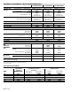
BLOWER/WATTS DATA G43UF−24B−045 PERFORMANCE (Less Filter) External Static Pressure High in. w.g. Pa cfm L/s Watts 0.00 0 1125 530 425 0.10 25 1115 525 410 0.20 50 1090 515 395 0.30 75 1060 500 380 0.40 100 1020 480 365 0.50 125 970 460 345 0.60 150 920 435 335 0.70 175 860 405 315 0.80 200 760 360 295 0.
BLOWER/WATTS DATA G43UF−48C−090 PERFORMANCE (Less Filter) Air Volume / Watts at Different Blower Speeds External Static Pressure Medium−High Medium−Low High in. w.g. Pa cfm L/s Watts cfm L/s Watts cfm L/s Watts 0.00 0 2180 1030 930 1835 865 790 1520 715 630 0.10 25 2135 1005 885 1825 860 750 1510 710 610 0.20 50 2085 985 840 1810 855 720 1505 710 580 0.30 75 2030 955 800 1775 835 685 1500 705 565 0.40 100 1940 915 760 1735 820 650 1480 700 535 0.50 125 1865 880 725 1660 785 600 1430 675 505 0.
BLOWER/WATTS DATA G43UF−60D−135 PERFORMANCE (Less Filter) − Single Side Return Air − Air volumes in bold require field fabricated transition to accommodate 20 x 25 x 1 in. (508 x 635 x 25 mm) air filter in order to maintain proper air velocity. Air Volume / Watts at Different Blower Speeds External Static Pressure Medium−High Medium−Low Low High in. w.g. Pa cfm L/s Watts cfm L/s Watts cfm L/s Watts cfm L/s Watts 0.00 0 2665 1260 1440 2325 1095 1100 1865 880 890 1410 665 690 0.
Visit us at www.lennox.com For the latest technical information, www.lennoxdavenet.com Contact us at 1−800−4−LENNOX NOTE − Due to Lennox’ ongoing committment to quality, Specifications, Ratings and Dimensions subject to change without notice and without incurring liability. Improper installation, adjustment, alteration, service or maintenance can cause property damage or personal injury. Installation and service must be performed by a qualified installer and servicing agency. ©2005 Lennox Industries Inc.