
User Guide
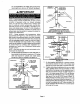
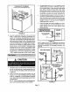

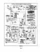

Inches (mm)
Front View
[
34
9
_, EXHAUST
I '10" VENT
= _ NOTE - Enclosed ex_us_ pipe _s
insuleted w;th _F2 i,_Ch(13 ram)
INTAKE foam insu_abon If in_al(ear_ ex-
VENT hsusl I_pes am reversed, sl=land
r_move foam instJlat_ot_ and
Ii teat)ply to OUmr vent Exhaust
vent mr=st be insulated
Side View
4
USTVENT
o
iNTAKE
VENT
E
VENT TERMINATIONS
MODEL WTKX (30GT9)
EXTENSION RISER FOR GRADE CLEARANCE
FIGURE 19
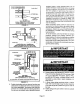
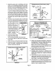
G32Q VENTING IN EXISTING CHIMNEY
NOTE - Do not dischal_e exhaust gases dit ently into or vent stack.
II ventCal discharge through at, ex_6ng unused chimney or stack ts require<J,
i_sertpipingintgde chlm,'.eyurdilthe pipeopenend Is abovetopof _y and
termimlte as iltusttstad. I. any extedor po(tlon of ¢ilrmney, the exhaust vent must
be insulated.An alternatemethodis to flitthe chimneywithvetrmc.ulitoor equal
to take advantage of its acoustic and thermal properties,
FIGURE 20
Condensate Piping
This unit is designed for either right- or left-side exit of
condensate piping. Route the condensate drainiine only
within the conditioned space: this prevents possible
freezing of the condensate, which would block the drain-
line. Use an electric heat cable if you route the conden-
sate line through unconditioned areas.
A CAUTION
1 - Determine which side condensate will exit the unit.
2- Connect 1/2 inch (13 mm) plastic pipe plug (pro-
vided) in the unused end of the condensate trap.
Install plug so that it is sealed water tight yet able to
be removed. Do not permanently seal the connec-
tion. Teflon tape is recommended to seal joint. See
figure 21.
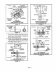
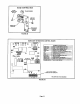
CONDENSATE ASSEMBLY
(For leftor rightinstallation)
COLD
COMBUSTION AIR HEADER
INDUCER BRACKET BOX
ADAPTER
ELBOW
CONDENSATE TRAP
NIPPLE BOOTORCAP
ADAPTER
FIGURE 2t
3 - Use the providedcondensate drain adapter (3/4" x
1/2") and a field-providednipple to carry drainage
outside the cabinet. If a fieldsubstitute is needed, 1/2
inch CPVC x 1/2 inch MPT adapter and 1/2 inch
CPVC is acceptable for use.
4 - Glue nipple to the adapter using the procedures out-
lined in the "Joint Cementing Procedures" section.
The nipple/adapter assembly should be connected
in a non-permanentmanner and must be water tight.
Teflon tape is recommended to seal the joint.
For Right-Hand Side Condensate Exit:
Install the nipple/adapter assembly from the out-
side of the cabinet and insert the adapter intothe
threaded opening in the condensate trap.
For Left-Hand Side Condensate Exit:
Insert nipple/adapterassemblyfrom the left hand
side of the cabinet and through the combustion air
inducer mounting structure into the threaded
opening in the condensate trap.
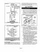
5 - Connect field-supplied plumbing to nipple and route
to open drain. Plumbing should be vented to a point
higher than the condensing coil. See figure 22.
Page14