INSTALLATION INSTRUCTIONS PRODUCT LITERATURE 2005 Lennox Industries Inc. Dallas, Texas G24-200 UPFLOW GAS FURNACE Direct Spark Ignition 503,613M 8/2005 Supersedes 7/2003 Litho USA Table of Contents RETAIN THESE INSTRUCTIONS FOR FUTURE REFERENCE G24−200 Unit Dimensions . . . . . . . . . . . . . . . . . . . . . . 2 G24−200 Parts Arrangement . . . . . . . . . . . . . . . . . . . . 4 G24−200 Gas Furnace . . . . . . . . . . . . . . . . . . . . . . . . . 6 Shipping and Packing List . . . . . . . . . . . .
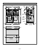
G24−200 Unit Dimensions − inches (mm) 52-1/2 (1334) VENT OUTLETS VENT OUTLETS 10-1/2 (267) 17 (432) 5/8 (16) 5-1/2 (140) 9 (229) Either Side 4-1/4 (108) Either Side 53 (1346) CONTROL BOX SUPPLY AIR OPENING 29-1/4 (743) 17 (432) 2 (51) HEAT EXCHANGER AIR FLOW GAS PIPING INLET Either Side) ELECTRICAL INLET (Either Side) BLOWER MOTOR 7/8 (22) 50-3/4 (1289) Bottom Return Air Opening 7/8 (22) FRONT VIEW 50-3/8 (1280) 1 (25) Supply Air Opening BACK VIEW 1-1/16 (27) 1 (25) 50-1/2 (1283)
G24−200 Filter Box Dimensions − inches (mm) AIR FLOW 5 (127) 4-3/4 (121) AIR FLOW 1 (25) 26-1/4 (667) 5 (127) OPENING SAME BOTH SIDES 32 (813) 1 (25) *OPTIONAL FILTER BOX *NOTE Return air filter box may be installed at back or bottom of furnace.
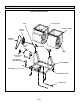
G24−200 Parts Arrangement G24−200 HEAT SECTION AND CABINET * (THIS UNIT CONTAINS TWO HEAT SECTIONS. EACH HEAT SECTION CONTAINS ONE OF THESE ITEMS.
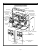
G24−200 Parts Arrangement Continued G24−200 BLOWER SECTION SHAFT CUT−OFF PLATE BLOWER HOUSING BLOWER PULLEY DRIVE BELT (Drive Kit) MOTOR (Drive Kit) BEARING WHEEL MOTOR PULLEY (Drive Kit) MOTOR BASE ADJUSTMENT ARM BASE ASSEMBLY MOTOR BASE VIBRATION ISOLATOR LOCATING ROD Page 5
Use only the type of gas approved for use with this furnace. Refer to unit nameplate. G24−200 Gas Furnace The G24−200 upflow gas furnace is for use with natural gas only. Each G24−200 requires the installation of a separately ordered drive kit. The available drive kits are listed in tables 10 and 15. Provided in each drive kit is the following: the furnace’s blower motor, its 24 volt control transformer, and (in non-208/230 volt models) an autotransformer for each of the furnaces’s induced draft blowers.
For installation in a residential garage, the furnace must be installed so that the burner(s) and the ignition source are located no less than 18 inches (457 mm) above the floor. The furnace must be located or protected to avoid physical damage by vehicles. When a furnace is installed in a public garage, hangar, or other building that has a hazardous atmosphere, the furnace must be installed according to recommended good practice requirements and current National Fuel Gas Code or CSA B149.1 standard.
This furnace design has not been CSA international certified for installation in mobile homes, recreational vehicles, or outdoors. WARNING The blower access panel must be securely in place when the blower and burners are operating. Gas fumes, which could contain carbon monoxide, can be drawn into living space resulting in personal injury or death. General These instructions are intended as a general guide and do not supersede local codes in any way.
infiltration. If the furnace is located in a building of tight construction with weather stripping and caulking around the windows and doors, follow the procedures in the air from outside section. CAUTION Insufficient combustion air can cause headaches, nausea, dizziness or asphyxiation. It will also cause excess water in the heat exchanger resulting in rusting and premature heat exchanger failure. Excessive exposure to contaminated combustion air will result in safety and performance related problems.
When ducts are used, they shall be of the same cross−sectional area as the free area of the openings to which they connect. The minimum dimension of rectangular air ducts shall be no less than 3 inches (75 mm). In calculating free area, the blocking effect of louvers, grilles, or screens must be considered.
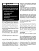
EQUIPMENT IN CONFINED SPACE ALL AIR FROM OUTSIDE (All Air Through Ventilated Attic) CHIMNEY OR GAS VENT VENTILATION LOUVERS (Each end of attic) OUTLET AIR G24−200 FURNACE INLET AIR (Ends 12 in. above bottom) NOTE−The inlet and outlet air openings shall each have a free area of at least one square inch (645 mm2) per 4,000 Btu (1.17 kW) per hour of the total input rating of all equipment in the enclosure.
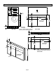
7 − Install the filters and the filter access door. BOTTOM RETURN AIR FILTER BOX INSTALLATION UNIT 2-3/4 (70) 29-1/4 (743) Furnace 27-1/4 (692) Opening 1 (25) 4-3/4 (121) ÎÎÎÎ ÎÎÎÎ ÎÎÎÎ 26-1/4 (667) Filter Box Opening AIR FLOW ADHESIVEBACKED FOAM TAPE 26-1/8 (664) x 50-5/8 (1286) RETURN AIR PLENUM 1 (25) FILTER BOX ÎÎ ÎÎ ÎÎ PLATFORM Floor Opening INCHES (mm) SIDE VIEW FIGURE 5 WARNING Improper installation of the furnace can result in personal injury or death.
B − Rear Return Air (Refer to figure 6) Duct System REAR RETURN AIR FILTER BOX INSTALLATION Size and install supply and return air duct system using industry-approved standards that result in a quiet and lowstatic system with uniform air distribution. ADHESIVE-BACKED FOAM TAPE (Apply to filter box) UNIT Supply Air Plenum Furnaces installed without a cooling coil require the installation of a removable access panel in the supply air duct.
Example: Deflection distance of a 400mm span would be 6mm. TYPICAL MOTOR/DRIVE INSTALLATION 3 − Measure the belt deflection force. For a used belt, the deflection force should be 5 lbs. (35kPa). A new belt deflection force should be 7 lbs. (48kPa). MOTOR MOTOR PULLEY A force below these values indicates an under-tensioned belt. A force above these values indicates an over-tensioned belt.
Venting Using a Masonry Chimney The following additional requirements apply when a lined masonry chimney is used to vent a G24−200 furnace: A type B1 vent or masonry chimney liner shall terminate above the roof surface with a listed cap or a listed roof assembly according to the terms of their respective listings and the vent manufacturer’s instructions. Masonry chimneys used to vent Category I central furnaces must be either tile-lined or lined with a listed metal lining system or dedicated gas vent.
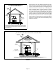
COMMON VENTING USING TILE−LINED INTERIOR MASONRY CHIMNEY AND COMBINED VENT CONNECTOR NOTE 1 − Refer to provided venting tables for installations in the USA and the venting tables in current CSA−B149.1 for installations in Canada. MIN. LENGTH = AS SHORT AS PRACTICAL. FOR MAX. LENGTH SEE NOTE 1 INTERIOR TILE−LINED MASONRY CHIMNEY JOIN HEAT SECTIONS WITH A ’TEE−Y’ VENT CONNECTOR SEE NOTE 2 Note 2 − Either single-walled or double-walled vent connector may be used.
10− A vent connector shall be supported without any dips or sags and shall slope a minimum of 1/4inch (6.4 mm) per linear foot (305 mm) of connector, back toward the appliance. See local and national installation codes for support intervals and methods. National installation code in the U.S.A is current edition of National fuel Gas Code (ANSI−Z223.1/NFPA54). National installation codes in Canada are current editions of CSA−B149 codes.
TABLE 3 CAPACITY OF TYPE B DOUBLE-WALL VENTS WITH TYPE B DOUBLE-WALL CONNECTORS SERVING A SINGLE CATEGORY I APPLIANCE Vent and Connector Diameter − D (inches) Height H (feet) 6 8 10 15 20 30 Lateral L (feet) 3 Inch 4 Inch 5 Inch 6 Inch Appliance Input Rating in Thousands of Btu Per Hour MIN MAX MIN MAX MIN MAX MIN MAX 0 0 78 0 152 0 251 0 375 2 13 51 18 97 27 157 32 232 4 21 49 30 94 39 153 50 227 6 25 46 36 91 47 149 59 223 0 0 84 0 165 0 276 0
TABLE 4 CAPACITY OF TYPE B DOUBLE-WALL VENTS WITH SINGLE-WALL METAL CONNECTORS SERVING A SINGLE CATEGORY I APPLIANCE Vent and Connector Diameter − D (inches) Height H (feet) 6 8 10 15 20 30 Lateral L (feet) 3 Inch 4 Inch 5 Inch 6 Inch Appliance Input Rating in Thousands of Btu Per Hour MIN MAX MIN MAX MIN MAX MIN MAX 0 38 77 59 151 85 249 126 373 2 39 51 60 96 85 156 123 231 4 NR NR 74 92 102 152 146 225 6 NR NR 83 89 114 147 163 220 0 37 83 58 164
TABLE 5 CAPACITY OF TYPE B DOUBLE-WALL VENTS WITH TYPE B DOUBLE-WALL CONNECTORS SERVING TWO OR MORE CATEGORY I APPLIANCES VENT CONNECTOR CAPACITY Vent Height H (feet) 6 8 10 15 20 30 Vent and Connector Diameter − D (inches) Connector Rise R (feet) 4 Inch 5 Inch 6 Inch 7 Inch Appliance Input Rating in Thousands of Btu Per Hour MIN MAX MIN MAX MIN MAX MIN MAX 1 35 66 46 106 58 164 77 225 2 37 75 48 121 60 183 79 253 3 38 81 49 132 62 199 82 275 1 35 72 49 11
TABLE 7 CAPACITY OF TYPE B DOUBLE-WALL VENT WITH SINGLE-WALL METAL CONNECTORS SERVING TWO OR MORE CATEGORY I APPLIANCES − VENT CONNECTOR CAPACITY Vent Height H (feet) 6 15 30 Vent and Connector Diameter − D (inches) Connector Rise R (feet) 4 Inch 5 Inch 6 Inch 7 Inch Appliance Input Rating in Thousands of Btu Per Hour MIN MAX MIN MAX MIN MAX MIN MAX 1 NR NR NR NR NR NR 207 223 2 NR NR NR NR 168 182 215 251 3 NR NR 121 131 174 198 222 273 1 79 87 116 138 177
Testing for Proper Venting and Sufficient Combustion Air (Non−Direct Vent Applications Only) WARNING CARBON MONOXIDE POISONING HAZARD! Failure to follow the steps outlined below for each appliance connected to the venting system being placed into operation could result in carbon monoxide poisoning or death. The following steps shall be followed for each appliance connected to the venting system being placed into operation, while all other appliances connected to the venting system are not in operation.
VENT TERMINATION CLEARANCES FOR INSTALLATIONS IN THE USA AND CANADA* − VENT TERMINATION − AIR INLET OF OTHER APPLIANCE C less than 10 ft (3.048M) D F D E G A − Clearance above grade − 12 in. (305mm) minimum. B − Clearance to window or door − for vent installations in USA − 48 in. (1219mm) minimum horizontal and below, 12 in. (305mm) minimum above. for vent installations in Canada − 12 in. (305mm) minimum for appliances 100,000 Btuh (30 kW); 36 in. (0.
Horizontal Venting This furnace design is certified by CSA international for horizontal venting through an outside wall, only with the use of two Field Controls Company Model SWG-4L sidewall venting kits, available from any Lennox Dealer Service Center. No other Field brand venting kits or any other manufacturer’s venting kits are acceptable. Horizontal venting of this furnace without the use of the above stated kits is prohibited.
Gas Piping NOTE − The flexible connector supplied with the unit must not be modified and must be installed between the two combination gas controls. 1 − Piping can be installed to enter either side of cabinet. Refer to figure 13. Left-Side Installation − Install flexible connector (supplied with unit) between gas valves and connect supply piping as shown. Right-Side Installation − a − Remove tee and 1/2 in. NPTx1/2 in. male brass fitting from left side gas valve. b − Remove 1/2 in.
TABLE 9 GAS PIPE CAPACITY − FT3/HR (KL/HR) Length of Pipe - Feet (m) Nominal Iron Pipe Size Inches(mm) Internal Diameter Inches(mm) 10 (3.048) 20 (6.096) 30 (9.144) 40 (12.192) 50 (15.240) 60 (18.288) 70 (21.336) 80 (24.384) 90 (27.432) 100 (30.480) 1/4 (6.35) .364 (9.246) 43 (1.13) 29 (.82) 24 (.68) 20 (.57) 18 (.51) 16 (.45) 15 (.42) 14 (.40) 13 (.37) 12 (.34) 3/8 (9.53) .493 (12.522) 95 (2.69) 65 (1.84) 52 (1.47) 45 (1.27) 40 (1.13) 36 (1.02) 33 (.73) 31 (.88) 29 (.
those where a 208/230 volt power supply is used, an autotransformer is required to power each of the induced draft blowers. These transformer(s) are provided in the drive kit which has been selected for use with the furnace. Transformer part numbers and voltages are given in table 10. Install the transformer(s) in the control box using the holes pre-drilled for them.
G24−200 FIELD WIRING DIAGRAM (120V SINGLE PH 60HZ) PRIMARY LIMIT COMBUSTION AIR BLOWER COMBUSTION AIR BLOWER IGNITION CONTROL BOARD GAS VALVE PRIMARY LIMIT IGNITION CONTROL BOARD GAS VALVE DOOR INTERLOCK 1 2 3 L1 4 DOOR INTERLOCK J84 BLOWER DECK L1 RED L3 PLUG RED L3 BLUE MAKE-UP BOX RED RED MAKE−UP BOX RED WHITE RED 2 7 GROUND LUG 2 BLUE (Alternate make-up box left side) REMOVE FACTORYINSTALLED JUMPER IN TWO-STAGE MODE R3 See Note 2 BLACK WHITE BLACK TERMINAL STRIP TB34 See
G24-200 FIELD WIRING DIAGRAM P UNITS − 208/230V 1PH 60 HZ Y UNITS − 208/230V 3PH 60HZ COMBUSTION PRIMARY LIMIT AIR BLOWER COMBUSTION AIR BLOWER PRESSURE SWITCH IGNITION CONTROL BOARD GAS VALVE PRIMARY LIMIT PRESSURE SWITCH IGNITION CONTROL BOARD GAS VALVE FLAME ROLLOUT SWITCH Three phase shown.
G24−200 FIELD WIRING DIAGRAM G UNITS − 460V 3PH 60HZ J UNITS − 575V 3PH 60HZ COMBUSTION AIR BLOWER PRIMARY LIMIT GAS VALVE (Alternate make-up box right side) IGNITION CONTROL BOARD 1 2 3 4 RED BLUE BLACK RED WHITE WHITE BLACK RED RED RED RED MAKE−UP BOX T13 TRANSFORMER 460v: white − red 230v: white − black RED C GROUND LUG 2 7 L2 L3 T3 TRANSFORMER 460v: white − red 230v: white − black RELAY K109 BLOWER DECK L3 TERMINAL STRIP TB34 SEE NOTE 1 1 1 5 PRESSURE SWITCH IGNITION CONTROL B
SCHEMATIC WIRING DIAGRAM FOR G24−200 UNITS (120V SINGLE PHASE 60HZ ) FIGURE 18 Page 31
WIRING SCHEMATIC DIAGRAM FOR G24−200 P UNITS − 208/230V 1PH 60 HZ Y UNITS − 208/230V 3PH 60HZ G UNITS − 460V 3PH 60HZ J UNITS − 575V 3PH 60HZ FIGURE 19 Page 32
Placing Furnace Into Operation G24−200 units are equipped with two direct spark ignition systems − one for each heat section. Do not attempt to manually light burners on these furnaces. Each time thermostat calls for heat, the burners will automatically light. Unit Start−Up FOR YOUR SAFETY READ BEFORE LIGHTING WARNING Do not use this furnace if any part has been under water. A flood−damaged furnace is extremely dangerous. Attempts to use the furnace can result in fire or explosion.
12 −If the furnace does not light the first time (the gas line may not be fully purged), it will attempt up to two more ignitions before locking out. 13 −If lockout occurs, repeat steps 1 through 10. 14 −If the appliance will not operate, follow the instructions Turning Off Gas To Unit" and call your service technician or gas supplier. B − Turning Off Gas To Unit 1 − Set the thermostat to the lowest setting. 2 − Turn off all electrical power to the unit if service is to be performed.
Gas Pressure Adjustment High Altitude Information Gas Flow (Approximate) 1− Operate unit at least 15 minutes before checking gas flow. Determine the time in seconds for two revolutions of gas through the meter. (Two revolutions assures a more accurate time.) A portable LP gas meter (17Y44) is available for LP applications. 2− Divide the number of seconds by two and compare to the time in table 11. If manifold pressure is correct and rate is incorrect, check gas orifices for proper size and restriction.
Temperature Rise Burner Flame Adjustment Check the temperature rise and, if necessary, adjust the blower speed to maintain the temperature rise within the range shown on the unit rating plate. The G24−200 burner flame is not adjustable; however, the flame should be inspected at the beginning of each heating season. If necessary, clean the burners. Burner flame should be blue when burning natural gas. See figure 21.
2 − The table yields a value for design BHP and RPM. Setting blower CFM 3 − Select drive kit so that motor maximum BHP (as shown in table 15) exceeds the value from table13. Note − Turn electrical power off when adjusting motor pulley. Blower RPM adjustment is accomplished by changing the motor pulley opening. Loosen Allen screw and turn pulley clockwise to increase RPM or turn counterclockwise to decrease. Re-tighten Allen screw.
TABLE 14 ACCESSORY AIR RESISTANCE Model cfm Pleated Filter − 1 in. (25 mm) C17−090/120 Coil *Disposable Filter − 1 in. (25 mm) EMD17M−95 EMD17M−135 L/s in. w.g. Pa in. w.g. Pa in. w.g. Pa in. w.g. Pa in. w.g. Pa 2400 1135 0.14 35 0.17 42 0.05 12 .04 10 −−−− −−−− 2600 1225 0.16 40 0.18 45 0.06 15 .05 12 −−−− −−−− 2800 1320 0.19 47 0.20 50 0.07 17 .06 15 −−−− −−−− 3000 1415 0.22 55 0.22 55 0.08 20 .07 17 .03 7 3200 1510 0.24 60 0.23 57 0.
Repair Parts List The following repair parts are available through independent Lennox dealers. When ordering parts, include the complete furnace model number listed on the CSA international. rating plate Example: G24−200. Refer to page 4 and 5 for parts identification.
Troubleshooting HEATING SEQUENCE OF OPERATION WITH TWO-STAGE THERMOSTAT NOTE − THIS FURNACE FUNCTIONS WITH TWO INDEDPENDENTLY CONTROLLED HEAT SECTIONS. THE GRAY BOXES INDICATE COMPONENTS WHICH EFFECT BOTH HEAT SECTIONS SIMULTANEOUSLY. NORMAL HEATING MODE ABNORMAL HEATING MODE POWER ON THERMOSTAT CALLS FOR HEAT (W1 ENERGIZED) K13 RELAY ENERIZED. A3 (A12) IGNITION CONTROL LED ON. NO DETERMINE WHY AUTOMATIC-RESET S10 (S99) HIGH LIMIT OPEN.
HEATING SEQUENCE OF OPERATION WITH TWO-STAGE THERMOSTAT CONTINUED NORMAL HEATING MODE ABNORMAL HEATING MODE NO IS THE S10 (S99) HIGH LIMIT CLOSED? DETERMINE WHY AUTOMATIC-RESET S10 (S99) HIGH LIMIT OPEN. K20, (K123), K36 RELAYS MAINTAIN BLOWER OPERATION.
HEATING SEQUENCE OF OPERATION WITH SINGLE-STAGE THERMOSTAT NOTE − THIS FURNACE FUNCTIONS WITH TWO INDEPENDENTLY CONTROLLED HEAT SECTIONS. THE GRAY BOXES INDICATE COMPONENTS WHICH EFFECT BOTH HEAT SECTIONS SIMULTANEOUSLY. NORMAL HEATING MODE ABNORMAL HEATING MODE POWER ON THERMOSTAT CALLS FOR HEAT (W1 ENERGIZED) K13 AND K19 RELAY ENERIZED. (W1 AND W2 OF FURNACE TERMINAL STRIP JUMPERED.) A3 (A12) IGNITION CONTROL LED ON. NO DETERMINE WHY AUTOMATIC-RESET S10 (S99) HIGH LIMIT OPEN.
HEATING SEQUENCE OF OPERATION WITH SINGLE-STAGE THERMOSTAT CONTINUED NORMAL HEATING MODE IS THE S10 (S99) HIGH LIMIT CLOSED? ABNORMAL HEATING MODE NO DETERMINE WHY AUTOMATIC-RESET S10 (S99) HIGH LIMIT OPEN. K20, (K123), K36 RELAYS MAINTAIN BLOWER OPERATION. YES IS W1 DEMAND OF THERMOSTAT SATISFIED? YES A3 (A12) LED OFF SECOND-STAGE OF GV1 (GV3) GAS VALVE CLOSES AFTER APRROXIMATELY 3 SEC. AND THEN FIRST-STAGE CLOSES. B6 (B15) COMBUSTION AIR BLOWER OFF. B3 SYSTEM BLOWERS OFF AFTER 150 SEC DELAY.
COOLING SEQUENCE OF OPERATION FOR TWO CONDENSING UNITS FOR A SINGLE CONDENSING UNIT THERMOSTAT CALLS FOR COOLING (Y1 POWERED) THERMOSTAT CALLS FOR COOLING (Y1 POWERED) COOLING CONTACTOR OF FIRST-STAGE CONDENSING UNIT CLOSES AND SYSTEM BLOWERS START. COOLING CONTACTOR OF CONDENSING UNIT CLOSES AND SYSTEM BLOWERS START. IS Y1 DEMAND SATISFIED? HAS ROOM AIR TEMPERATURE CONTINUED TO RISE ABOVE THE THERMOSTAT"S Y2 SET POINT? YES YES COOLING UNIT CONTACTOR OPENS AND B3 SYSTEM BLOWERS OFF.