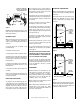
INSTALLATION INSTRUCTIONS ELITE™ SERIES 41" Wood Burning Fireplaces P/N 504,217M REV. E 04/2007 MODELS LA41CF LA41TCF This installation manual will enable you to obtain a safe, efficient and dependable installation of your fireplace system. Please read and understand these instructions before beginning your installation. Do not alter or modify the fireplace or its components under any circumstances.
TABLE OF CONTENTS Safety Rules .................................... page Tools and Building Supplies ............ page Precautions ..................................... page Introduction ..................................... page Clearances/Height Requirements ..... page Chimney System ............................. page Assembly Outline ............................. page Location of Fireplace ....................... page Assembly Steps ............................... page Preinstallation Notes .............
PRECAUTIONS Note: These fireplace systems are not difficult to install. However, in the interest of safety, it is recommended that the installer be a qualified or certified “tradesman” familiar with commonly accepted fireplace installation and safety techniques as well as prevailing local codes.
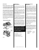
Note: Do not insulate the chase cavity with blown or fill type insulation materials. Insulate Joists Same As Ceiling Note: Local codes may not require firestopping at the ceiling levels for outside chase installations. However, it is recommended for safety and the reduction of heat loss.
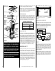
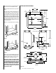
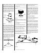
Black Portion Of Frame Not To Be Covered With Combustible Materials Wall Covering 20” The fireplace may be positioned and then the framing built around it, or the framing may be constructed and the fireplace positioned into the opening. 45° 1” Door Opening 20” Be sure fireplace rests on a solid continuous floor or platform with appropriate framing for support and so that no cold air can enter the room from under the fireplace.
Note: Safety strips are not required when fireplace rests on a noncombustible surface. FIREPLACE SPECIFICATIONS 15" (381 mm) Note: Install the hearth extension only as illustrated. 7 ¹⁄₈" (181 mm) The safety strips should extend from front of the fireplace at least 1 ¹⁄₂" and should extend to be at least flush with the sides.
Note: The framed depth, 28 ¹⁄₈" (714 mm) from a framed wall, must always be measured from a finished surface. If a wall covering such as drywall is to be attached to the rear wall, then the framed depth must be measured from the drywall surface. It is important that this dimension be exact. If the appliance is to be elevated above floor level, a solid continuous platform must be constructed. The header may rest on the top metal spacers, but must not be notched to fit around them.
Step 4. Fireplace should be secured to side framing members using the full length nailing tabs at the top and bottom of the fireplace front face. Use 8d nails or equivalent (Figure 17 ). For remodeling, plumb to center of flue collar from ceiling above, drive nail through ceiling from below to mark position, then mark and cut to passage from above ceiling (around nail) (Figure 18 ). Then plumb from ceiling or roof level directly above hole which has just been completed.
Step 4. Note: Chimney sections are constructed with a unique locking tab design, which ensures an immediate, tight assembly between sections. Plan your chimney requirements carefully before assembly as chimney is difficult to disassemble after installation. If disassembled, the tabs might become damaged. Be certain tabs are properly formed to ensure locking tabs engage properly. Security Chimneys FTF10 chimney system is a two piece chimney, which snap together from the fireplace up.
Step 8. The standard Security Chimneys FTF10 roof flashing assemblies include a storm collar. Slide the storm collar over outer chimney, rest on flashing spacers and align with top surface of flashing. Insert tab in slot, pull tight and bend tab back over slot. Seal storm collar to outer chimney with roof caulking or mastic around entire circumference of pipe. Also add extra roof caulking to the tab/slot area to seal completely against water penetration (Figure 29 ).
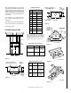
MULTIPLE TERMINATIONS 3. The effective heights of the components are: If more than one termination is located in the same chase or within the same general proximity, we suggest they should be separated in distance at least 24" horizontally from flue center to flue center and stacked or staggered vertically at least 18" apart, from the termination of one smoke exit to the termination of another smoke exit (Figure 33 ).
FTF10 VERTICAL ELEVATION CHART Inches 11 17 21 27 33 35 37 43 51 55 61 67 69 79 85 89 95 103 113 119 123 129 137 147 153 158 164 171 182 188 192 198 206 215 222 226 232 240 250 256 260 266 274 284 290 294 300 308 318 324 328 334 342 352 ¹⁄₄ ¹⁄₄ ¹⁄₄ ¹⁄₄ ¹⁄₄ ¹⁄₄ ¹⁄₄ ¹⁄₄ ¹⁄₄ ¹⁄₄ ¹⁄₄ ¹⁄₄ ¹⁄₂ ¹⁄₂ ¹⁄₄ ¹⁄₂ ¹⁄₂ ³⁄₄ ³⁄₄ ¹⁄₂ ³⁄₄ ³⁄₄ ³⁄₄ ³⁄₄ ¹⁄₄ ¹⁄₄ ¹⁄₄ ¹⁄₄ ¹⁄₂ ¹⁄₂ ¹⁄₄ ¹⁄₂ ¹⁄₂ ³⁄₄ ³⁄₄ ¹⁄₂ ³⁄₄ ³⁄₄ ³⁄₄ ³⁄₄ ³⁄₄ ³⁄₄ Number Of FTF10 Chimney Lengths Feet/Inches 0 1 1 2 2 2 3 3 4 4 5 5 5 6 7 7 7 8 9 9 10 10 11 12 12 13
FTF10 OFFSET ELEVATION CHART A Offset B Height FTF10-ES30 Offset/Return FTF10-S4 Number of FTF10 Chimney Sections (Inches) (Inches) Elbow Set Stabilizer 12" 18" 36" 1 1 1 1 1 1 1 1 1 1 1 1 1 1 1 1 1 1 1 1 1 1 1 1 1 1 1 1 1 1 1 1 1 1 1 1 1 1 1 1 1 1 0 0 0 0 0 0 0 0 0 0 0 0 0 0 0 0 0 0 0 0 0 0 0 0 0 0 0 0 0 0 0 1 1 1 1 1 1 1 1 1 1 1 0 1 0 2 1 0 0 2 1 1 0 0 2 4 1 3 0 0 2 1 1 3 0 0 2 1 1 0 0 2 1 1 0 2 1 1 0 2 1 3 0 1 0 0 1 0 1 2 0 1 2 0 3 1 0 1 1 0 2 0 1 4 0 1 3 1 0 5 1 2 0 1 2 0 1 0 3 1 2 1 0 1
Note: See Framing and Dimension Chart for the sizes of the ceiling and roof openings. The size of the roof opening varies with the degree of pitch of the roof. Offset Elbow Assembly Offset elbows install the same as chimney sections. First, snap the inner section INTO the preceding inner section of flue. Check connection by pulling up slightly to ensure a tight fit. Next, the outer sections snap lock OVER the preceding outer section of chimney.
These fireplaces have been marked with a maximum rating of 40,000 BTU to assure that homeowners do not exceed the allowable limits for all allowed installations of mantles. NEVER INSTALL AN UNVENTED GAS LOG SET WITH A BTU GREATER THAN 40,000. CAUTION: WHEN USING THE DECORATIVE GAS APPLIANCE, THE FIREPLACE DAMPER MUST BE SET IN THE FULLY OPEN POSITION. CAUTION: PLUMBING CONNECTIONS SHOULD ONLY BE PERFORMED BY A QUALIFIED, LICENSED PLUMBER.
Note: Any noncombustible material whose k value is less than .84 or whose r value is more than 1.19 is acceptable. If the fireplace is installed on a combustible floor, use the metal safety strips (provided) on the floor extending half under the fireplace and half under the hearth extension. A wall shield is required where a continuous perpendicular side wall is within 15" of the fireplace opening (see Figure 44 ).
Answer - The minimum required thickness of the Micore 160 is .417”, therefore round up to nearest standard thickness available which is 1/2”. Calculating Minimum Thickness if Multiple Materials are Used Listed Material At times it is important to know what combination of materials are acceptable for use as floor protection. The “R values” are used to determine acceptable combinations of materials because “R values” are additive where r and k values are not. k (per inch) Listed Material .
Example: Given that the required “R value” for a suitable hearth extension used must be equal to or greater than: INSTALLATION COMPONENTS The following items are available for use in the installation of this appliance. “R” = r x TL = 3.70 x 1" = 3.70. If it is desired to elevate a marble hearth extension to a level of 5" or more above the floor surface.
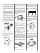
INSTALLATION COMPONENTS Round Termination Firestop Spacer (Flat) Locking Band Storm Collar 63L423 63L36 63L60 63L59 FTF10-CTD Chimney Section 63L16 63L17 63L18 FTF10-12 FTF10-18 FTF10-36 Chase Termination (Square) 63L52 FTF10-CT2 Flashing 63L40 63L41 F10F6 F10F12 Chase Termination (Round) 63L46 FTF10-CTDT Chase Termination (Square) 63L49 FTF10-CT1 Stabilizer 63L26 FTF10-S4 F10FS-2 FLB FSC NOTE: DIAGRAMS & ILLUSTRATIONS NOT TO SCALE.
Lennox Hearth Products reserves the right to make changes at any time, without notice, in design, materials, specifications, prices and also to discontinue colors, styles and products. Consult your local distributor for fireplace code information. Printed in U.S.A. © 2000 by Lennox Hearth Products 20 P/N 504,217M REV. E 04/2007 NOTE: DIAGRAMS & ILLUSTRATIONS NOT TO SCALE.