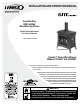
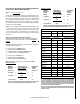
INSTALLATION AND OPERATION MANUAL Free-Standing EPA Certified Wood-Burning Stoves Retain These Instructions For Future Reference P/N 775,080M, Rev. G, 09/2007 Model CI2000HT Shown Spectra™ Series Wood Stoves Models CI1000HT and CI2000HT A French manual is available upon request. Order P/N 775,080CF. Ce manuel d’installation est disponible en francais, simplement en faire la demande. Numéro de la pièce 775,080CF. US CI1000HT Report #132-S-03-2 CI2000HT Report #132-S-05-2.
IMPORTANT SAFETY AND WARNIING INFORMATION read THIS MANUAL IN ITS ENTIRETY and understand these Rules to follow for safety. CAUTION Read this manual thoroughly before starting installation. For your safety, follow the installation, operation and maintenance instructions exactly without deviation. Failure to follow these instructions may result in a possible fire hazard and will void the warranty. If this appliance is not properly installed, a house fire may result.
Congratulations! Packaging List When you purchased your new wood stove, you joined the ranks of thousands of concerned individuals whose answer to their home heating needs reflects their concern for aesthetics, efficiency and our environment. We extend our continued support to help you achieve the maximum benefit and enjoyment available from your new wood stove. It is our goal at Lennox to provide you, our valued customer, with an appliance that will ensure you years of trouble free warmth and pleasure.
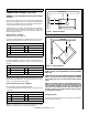
SELECTING A LOCATION CAUTION The design of your home and where you place your stove will determine its value as a source of heat. This type of appliance depends primarily on air circulation (convection) to disperse its heat, and therefore, a central location is often best. There are other practical considerations, which must be considered before a final selection of locations is made. • Existing Chimneys The body of these appliances are very heavy.
Floor Protection / Hearth Extension Using Alternate Material As Floor Protector - Model CI1000HT (USA only) Note: Also see Floor Protection above . The hearth pad or alternate material used as a floor/hearth protector must be constructed of a durable noncombustible material having an equal or better thermal conductivity value (lower k value) of k =.84 BTU/IN FT2 HR °F or a thermal resistance that equals or exceeds r = 1.19 HR °F FT2 IN/BTU with a minimum thickness of 1/2”.
Floor Protection / Hearth Extension Using Alternate Material As Floor Protector - Model CI1000HT (Canada only) Note: Also see Floor Protection above . The hearth pad or alternate material used as a floor/hearth protector must be constructed of a durable noncombustible material having an equal or better thermal conductivity value (lower k value) of k =.84 BTU/IN FT2 HR °F or a thermal resistance that equals or exceeds r = 1.19 HR °F FT2 IN/BTU with a minimum thickness of 1/2”.
Floor Protection - Model CI2000HT (USA and Canada) The floor protector must meet or exceed the minimum thermal requirements as defined on this Page (see Floor Protection / Hearth Extension Using Alternate Material As Floor Protector). If the floor protection is to be stone, tile, brick, etc., it must be mortared or grouted to form a continuous noncombustible surface.
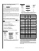
Floor Protection - Model CI2000HT (USA and Canada) Continued... COMBUSTIBLE WALL CLEARANCE – USA & Canada Listed Material k (per inch) Listed Material .84 KL r (per inch) 1.19 rL Listed Min. Thickness 1/2" (.5") TL ** Approved Alternate Materials for Floor/Hearth Protection Alternative Materials Thermal Values k (per inch) KM r (per inch) rM CLEARANCES - MODEL CI1000HT Minimum Thickness (rounded to nearest 1/8 inch) Min.
CLEARANCES - MODEL CI2000HT Combustible COMBUSTIBLE WALL CLEARANCE – USA & Canada There are listed clearances for your stove which were determined in a Laboratory test using various “classes” of stove pipe or chimney. Minimums are first established for the stove itself and increased based on how much heat is transferred by each class of pipe. Position the unit no closer than the minimum clearances to combustible materials. Check that no overhead cross members in the ceiling or roof will be cut.
Minimum / Maximum Flue Diameter: Minimum 6”, Maximum 10” INSTALLATION Types of Chimneys Chimney Connector Adapter The unit must be connected to either a code-approved masonry chimney with a flue liner, or a 6 inch diameter factory-built chimney complying with the requirements for Type HT chimneys in the standard UL 103. Use a chimney connector adapter to connect the chimney connector up to the chimney. The small ends of the chimney connector should all point down for a drip free installation.
Chimney Height Requirements CAUTION The chimney must extend 3 feet above the level of roof penetration and a minimum of 2 feet higher than any roof surface within 10 feet (see below). Check with your local building officials for any additional requirements for your area. Many structure fires have resulted when a slow burning fire has been left unattended for any extended period of time.
3) Drill a hole in the vent pipe per the draft gauge manufacturers instructions (to create a draft test port). Note: Hole location should be a minimum of 1 foot above flue outlet collar. Single Wall Pipe Using 6” Diameter Single Wall Connector Pipe 4) Start a fire (See How To Start And Maintain A Fire on Page 15). 5) After the fire is well established (20-25 minutes) and burning at a low setting, perform the draft test per the gauge manufacturer instructions. The draft gauge should read between .05 and .
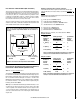
Combustible Wall Chimney Connector Pass-Throughs Refer to Figure 9 Double Wall Pipe (Approved for Model CI2000HT Only) Using 6” Diameter Type L-Vent Connector Pipe Termination Cap with Spark Arrestor 3 Feet Minimum Storm Collar Flashing Support Box Minimum of 12-15’ of Flue to achieve a stable draft. DVL Close Clearance Connector Pipe 7 Feet Minimum Floor Protector Figure 8 - Double Wall Pipe Method A. 12” (305 mm) Clearance to Combustible Wall Member: Using a minimum thickness 3.
Minimum Chimney Clearance to Brick & Combustibles – 2 in. (51mm) Min. Clearance 12 in. (304.8mm) of Brick Chimney Flue A Minimum Chimney Clearance from Masonry to Sheet Steel Supports & Combustibles – 2 in. (51mm) Min. Clearance 9 in. (228.6mm) Factory Built Chimney Length Chimney Length Flush with Inside of Flue Chimney Connector Use Chimney Mfrs. Parts to Attach Connector C h im n ey F lu e Air Space – 9 in. (228.6mm) Min.
Adjusting Burn Rate: How To Start And Maintain A Fire The primary air draft control located above the front door can be adjusted to the right for higher temperatures and to the left for lower temperatures. 1. Using the Air Control Tool (provided), open the Start-Up Air Control (see Start-Up Air Control, on this Page). Generally, you will want to set the draft control somewhere in the low or medium range 2.
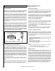
Front Ash Removal Door And Side Fuel Loading Door CAUTION Primary Air Control When opening the doors, do not extend them beyond their normal travel. Overextending the doors to a further open position can put excessive stress on the hinge area of the doors which may result in breakage. Secondary Air Tubes (2) Permanent Secondary Combustion Air Intake. Secondary air is delivered through this opening to ignite secondary gases. There is no adjustment control for this intake. Permanent Primary Air Intake.
Refueling Burn-In Period Your stove finish is a high temperature paint that requires time and temperature to completely cure. We recommend that you ventilate the house during the initial burns. The paint emits non-toxic odors during this process. CAUTION KEEP YOUR HOUSE WELL VENTILATED DURING THE CURING PROCESS TO PREVENT ACTIVATION OF YOUR HOME SMOKE DETECTOR. Always check for high flames when opening a door by partially opening door for a few seconds before opening fully.
What is the best wood for the fire? Some woods are easier to light than others (i.e. hornbeam, beech, & oak do not light easily whereas aspen, birch and lime light easily but they do not last as long). Then come the softwoods and conifers. Regardless if you are burning a softer or harder wood, what is most important is that it is well-seasoned dry wood. Damp wood has far less heating power, this lowers the combustion temperature of the fire therefore, the output.
MAINTENANCE NEVER PLACE ASHES IN A CARDBOARD BOX OR ANY OTHER COMBUSTIBLE RECEPTACLE. WARNING Proper Disposal of Ashes: Do NOT clean the stove while it is hot! IMPORTANT Inspect the entire stove frequently for proper operation, fit and soundness of parts. If any malfunctioning, cracked, broken, or loose parts or other problems are noted, contact your dealer or qualified serviceman to inspect and repair the unit. Do not operate the unit if installed or functioning improperly.
Replacing Glass: 1. Open the door. Using a phillips screwdriver loosen the four (4) screws which secure the glass then carefully remove broken glass one piece at a time (protective leather gloves are recommended). 2. Remove screws and clips from doorframe and set aside. Door Frame 4 Ea. Clip Gaskets 4 Ea. Glass Clips Glass Gasket 4 Ea. Glass Clip Screws Removing Baffle for Cleaning Before flue can be cleaned, the baffle in the stove firebox must be removed.
TROUBLESHOOTING * When Fuel Door Is Opened, Smoke Enters Room 1. The primary air draft control is closed. 2. The chimney is too cool. Set the primary air draft control on “HIGH” for a few minutes before opening either fuel loading door. 3. Excess creosote will not only restrict your draft but it will create a risk of a creosote fire. Strictly adhere to maintenance requirements as outlined in this manual.
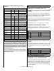
SPECIFICATIONS - Model CI1000HT Flue position Top Flue collar size 6” (152 mm) Approx. burn time 6 to 8 hours Maximum burn rate 87,301 BTU EPA BTU Range 11,500 – 55,000 BTU Emissions Rate (grams/hr) 4.42 grams Maximum Log length 18” (457 mm) Firebox Size 1.12 cu. feet Loading Front & Side Width (overall) 23-3/4” (604 mm) Depth (overall) 15-5/16” (389 mm) Height (to flue) 30” (762 mm) Height (to stove top) 27-1/4” (693 mm) Back to centerline of flue 6-7/16” (163 mm) Approx.
SPECIFICATIONS - Model CI2000HT FRONT VIEW Flue position Top Flue collar size 6” (152 mm) 29-1/8" (740 mm) Approx. burn time 6 to 8 hours 6" (152 mm) Maximum burn rate 96,662 BTU EPA BTU Range 11,923 – 60,897 BTU Emissions Rate (grams/hr) 2.72 grams Maximum Log length 22” (559 mm) Firebox Size 1.97 cu.
REPLACEMENT PARTS LIST - Models: CI1000HT & CI2000HT Item Cat. No.
REPLACEMENT PARTS LIST - Models: CI1000HT & CI2000HT Item Cat. No. Description 40M4501 Gasket Kit, 6 mm x 156 cm (14979) For Air Intake Slide & Glass & 4 ea. 6mm Glass Clip Gaskets (31856) 40M0201 Gasket Kit, Ashpan Door Rope (8 mm Dia. X 97 cm) 40M4201 Gasket Kit, Rope (10 mm Dia. x 146cm) Ashpan Door - CI2000HT, Side & Front Firebox Door - CI1000HT 40M4401 Gasket Kit, Rope (12 mm Dia.
REPLACEMENT PARTS - Models: CI1000HT & CI2000HT REPLACEMENT PARTS - Models: CI1000HT & CI2000HT (1) Front Firebox Door (CI1000HT & CI2000HT Series) (7) Left Lower Firebrick (CI2000HT Series) (4) Ashpan Door (CI2000HT Series) .79” / 20 mm thick (2) Side Loading Door (CI1000HT Series) 10.08” / 256mm 7.87” / 200 mm (5) Bottom Center Firebrick (CI2000HT Series) 7.87” x 200 mm 4.6” / 117 mm .79” / 20 mm thick (2) Side Loading Door (CI2000HT Series) (6) Bottom Side Firebrick (CI2000HT Series) 7.
REPLACEMENT PARTS - Models: CI1000HT & CI2000HT REPLACEMENT PARTS - Models: CI1000HT & CI2000HT (10) Right Lower Firebrick (CI2000HT Series) (14) Right Firebrick (CI1000HT Series) 4.72” / 120 mm 10.43” / 265 mm .79” / 20 mm thick 8.47” / 215 mm x 5.12” / 130mm (.98” / 25mm thick) (11) Upper Rear Firebrick (CI2000HT Series) (18) Fuel Grate Frame (CI2000HT Series) 7.87” / 200 mm 13.93” / 354 mm .
REPLACEMENT PARTS - Models: CI1000HT & CI2000HT REPLACEMENT PARTS - Models: CI1000HT & CI2000HT (20) Fuel Grate Support Bar (CI1000HT Series) (25) Front Firebox Door Hinge Pin (CI1000HT Series) (29) Log Guard (C1000HT Series) (26) Front Firebox Door Hinge Pin (CI2000HT Series) (30) Log Guard (CI2000HT Series) (21) Ash Removal Grate (CI1000HT Series) (22) Fuel Grate (CI1000HT Series) (27) Side Door Hinge Pin (CI1000HT & CI2000HT Series) (31) Left Air Column Assembly (CI1000HT Series) (23) Fuel Grate
REPLACEMENT PARTS - Models: CI1000HT & CI2000HT REPLACEMENT PARTS - Models: CI1000HT & CI2000HT (32) Left Air Column Assembly (CI2000HT Series) (35) Ashlip (CI1000HT & CI2000HT Series) (39) Flue Outlet Collar (CI1000HT Series) (36) Ashpan (CI1000HT & CI2000HT Series) (40) Flue Outlet Collar (CI2000HT Series) (32) Right Air Column Assembly (CI2000HT Series) Side View Top View (37) Baffle Assembly, Ceramic Fiber Brick (above secondary air tubes) (CI2000HT Series) (41) Fire Poker (CI1000HT & CI2000HT Se
REPLACEMENT PARTS - Models: CI1000HT & CI2000HT REPLACEMENT PARTS - Models: CI1000HT & CI2000HT (43) Secondary Air Tube Assembly (CI1000HT Series) (45) Air Control/Ash Pan Removal Tool (CI1000HT & CI2000HT Series) (48) Draft Module (Air Intake Slide) (CI2000HT Series) (46) Removable Door Opener Tool (CI1000HT & CI2000HT Series) (49) Rear Firebrick Retainers (CI2000HT Series) Side Retainers Not Shown (44) Secondary Air Tube Assembly (CI2000HT Series) (47) Draft Module (Air Intake Slide) (CI1000HT Serie
OPTIONAL ACCESSORIES - Models CI1000HT & CI2000HT Catalog No.
SAFETY/LISTING LABEL – Model CI1000HT CONTACT YOUR LOCAL BUILDING OR FIRE OFFICIALS ABOUT RESTRICTIONS AND INSTALLATION INSPECTION IN YOUR AREA CONTACTEZ LE BUREAU DE LA CONSTRUCTION OU LE BUREAU DES INCENDIES AU SUJET DES RESTRICTIONS ET DES INSPECTIONS D’INSTALLATION DANS VOTRE VOISINAGE Listed Room Heaters, Solid Fuel Type/ Appareil de Chauffage de Pièce, de Combustibles Solides FOR USE WITH SOLID WOOD FUEL ONLY / POUR USAGE AVEC LE BOIS SEULEMENT Serial No.
SAFETY/LISTING LABEL – Model CI2000HT CONTACT YOUR LOCAL BUILDING OR FIRE OFFICIALS ABOUT RESTRICTIONS AND INSTALLATION INSPECTION IN YOUR AREA CONTACTEZ LE BUREAU DE LA CONSTRUCTION OU LE BUREAU DES INCENDIES AU SUJET DES RESTRICTIONS ET DES INSPECTIONS D’INSTALLATION DANS VOTRE VOISINAGE Listed Room Heaters, Solid Fuel Type/Appareil de Chauffage de Pièce, de Combustibles Solides FOR USE WITH SOLID WOOD FUEL ONLY / POUR USAGE AVEC LE BOIS SEULEMENT Serial No.
EPA LABELS – CI1000HT and CI2000HT EPA LABELS – CI1000HT and CI2000HT 34 PAGE 38
OWNERSHIP RECORDS Dealer’s Name: Dealer’s Address: City: State: Zip Code: Serial Number: Date of Purchase: Date Installed: Notes: SERVICE AND MAINTENANCE LOG Service Service Service Date Technician Description 35
Warranty Your wood appliance is covered by a limited warranty (provided with appliance). Please read the warranty to be familiar with its coverage. Retain this manual. File it with your other documents for future reference. Product reference information We recommend that you record the following important information about your fireplace. Please contact your Lennox Hearth Products dealer for any questions or concerns. For the number of your nearest Lennox Hearth Products dealer, please call 1-800-9-Lennox.