CARE AND OPERATION INSTRUCTIONS EBVST B-Vent Gas Fireplaces P/N 875026M Rev. e 01/2011 MODELS This manual is part of a set of two supporting this product. Refer to P/N 850025M for Installation Instructions. Ce manuel est disponible en francais, simplement en faire la demande. Numéro de la pièce 875026CF. Table of Contents . . . . . . . . . . . . . . . . . . . . . . . . . . . . . . . . . . . . . Safety and Your Fireplace . . . . . . . . . . . . . . . . . . . . . . . . . . . . .
Thank you for your purchase. We appreciate your business! Please carefully read and follow all instructions in this manual. Pay special attention to all warnings and safety information. Following these safety, care, and operation instructions will help ensure many years of dependable and enjoyable service from your fireplace. • FREE SAFETY GUARD OFFER • The Lennox® SAFETY GUARD protects against severe burns and injuries by preventing direct contact with the front glass surface of your fireplace.
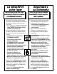
[FRENCH] La sécurité et votre foyer Toutes les parties de votre foyer Lennox Hearth Products deviennent EXTRÊMEMENT CHAUDES ! Afin d'éviter de vous brûler gravement ou de vous blesser, installez une grille ou une barrière physique pour empêcher tout contact direct avec la vitre. Pour commander un PANNEAU DE PROTECTION Lennox® GRATUIT pour votre foyer, consultez les détails dans la partie gauche.
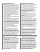
Important Safety Information L'information de sûreté importante 1. WARNING: Do not operate appliance with the glass front removed, cracked or broken. Replacement of the glass should be done by a licensed or qualified service person . 1. AVERTISSEMENT. Ne pas utiliser l’appareil si le panneau frontal en verre n’est pas en place, est craqué ou brisé. Confiez le remplacement du panneau à un technicien agréé 2. Do not use this appliance if any part has been under water.
HOMEOWNER’S INSTRUCTIONS - ATTACHING SAFETY-IN-OPERATION WARNINGS Attaching Safety-in-Operation Warnings Apposition des mises en garde relatives à la sécurité d’utilisation Colocación de advertencias de seguridad en operación Your fireplace has been furnished with safety instruction labels that are to be affixed to the operation and control point of the fireplace.
General Information The fireplace models covered in this manual are b-vented decorative fireplaces designed for residential application. The Millivolt appliances have a millivolt gas control valve with piezo ignition system. If any optional accessories which require electrical power are being installed, the electrical power must be provided at the time of appliance installation. The Electronic appliances are designed to operate on either natural or propane gas.
BTU Input These fireplaces are designed as supplemental heaters. Therefore, it is advisable to have an alternate primary heat source when installed in a dwelling. Millivolt Models - The millivolt appliances are manually controlled and feature a spark igniter (piezo) that allows the appliance's pilot gas to be lit without the use of matches or batteries. This system provides continued service in the event of a power outage.
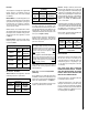
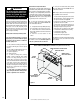
Operation and care of your appliance Refer to Figure 1 for access to the gas control valve. Millivolt appliances will be fitted with the gas control valve shown in Figure 2. WARNING Young children should be carefully supervised when they are in the same room as the appliance. Toddlers, young children and others may be susceptible to accidental contact burns. A physical barrier is recommended if there are at risk individuals in the house.
Variable Flame Height Adjustment Inlet Pressure Port Manifold Pressure Port IN OUT TPTH TP HI TH LO W OFF i t P IL O T ON P IL OT SIT Millivolt Gas Valve Main Gas Control Knob Note: The piezo ignitor is located on the modesty panel - refer to Figure 1. Figure 2 OFF ON CONTROL 2. When lit for the first time, this appliance will emit a slight odor for an hour or two. This is due to the “burn-in” of internal paints and lubricants used in the manufacturing process.
WARNING Do not operate the shutoff lever unless a complete outside combustion air system has been installed with your appliance. To open the outside air shutter, open the botttom control access panel, reach into the gap between the firebox bottom and the modesty panel, and pull the outside air control lever all the way out. The outside air shutter should be fully open when the fireplace is in use and completely closed when the fireplace is not being used.
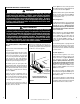
MAINTENANCE (See Maintenance Schedule, Page 25) Refer to the maintenance schedule for maintenance tasks, procedures, periodicity and by whom they should be performed. Always verify proper operation of the appliance after servicing. WARNING Turn off gas and electrical power to the fireplace and allow it to cool before cleaning or servicing the appliance. CAUTION: Wear gloves and safety glasses for protection while doing required maintenance. Verify proper operation after servicing.
Front Glass Enclosure Panel, Removal and Installation WARNING • Do not attempt to substitute the materials used on this door, or replace cracked or broken glass. • Handle this glass with extreme care! Glass is susceptible to damage – Do not scratch or handle roughly while reinstalling the glass door frame. • The glass door(s) of this appliance must only be replaced as a complete unit as provided by the manufacturer. Do not attempt to replace broken, cracked or chipped glass separately.
INSTALLATION STEPS: READ WARNINGS ON THIS PAGE BEFORE PROCEEDING. FOLLOW THE LOG PLACEMENT INSTRUCTIONS EXACTLY 1. Remove the front glass enclosure panel (see Glass Enclosure Panel Removal and Installation Instructions, Page 12 ). 2. Remove the following from firebox; log set, bag of embers and bag of vermiculite. Handle logs carefully to prevent breakage. 3. Ensure the Grate is properly installed in the firebox with the 4 legs of the grate fitting into the 4 dimples on the firebox floor. 4.
EBVPF And EBVST Log Placement 6 2 Log Number 4 1 2 3 4 5 6 Description Part Number Log, Corner Log, Rear/Left Log, Front/Left Log, Rear/Right Log, Front/Center Log, Center/Top 55M18 55M19 55M20 55M21 55M22 55M23 Catalog Number for the entire log set: 55M04 3 5 1 3 STEP 3 1 STEP 1 Position Groove At The Bottom Of Log (1) Over The Burner Log Support Bracket STEP 2 Log (3) Lays Over Logs 1 And 2 2 Place Bottom Hole Of Log (3) On Pin In Log (2).
EBVPF And EBVST Log Placement (Continued) 6 2 Log Number 4 1 2 3 4 5 6 Description Part Number Log, Corner Log, Rear/Left Log, Front/Left Log, Rear/Right Log, Front/Center Log, Center/Top 55M18 55M19 55M20 55M21 55M22 55M23 Catalog Number for the entire log set: 55M04 3 5 1 Position Small End Of Log (6) On The Notch Of Log (3) Here STEP 5 6 Position The Round End Of Log (6) Against The Notch Of Log (4) Here.
Burner Adjustments (QUALIFIED TECHNICIANS ONLY) Flame Appearance and Sooting Proper flame appearance is a flame which is blue at the base and becomes yellowish-orange in the body of the flame. When the appliance is first lit, the entire flame may be blue and will gradually turn yellowishorange during the first 15 minutes of operation. If the flame remains blue, or if the flame is orange with evidence of sooting (black tip), the air shutter opening may need to be adjusted.
Burner FLAME Adjustments WARNINGS • Air shutter adjustment should only be performed by a qualified professional service technician. • Ensure front glass panel are in place and sealed during adjustment. CAUTIONS • Soot will be produced if the air shutter is closed too much. Any damage due to sooting, resulting from improperly setting the air shutter, is not covered under the warranty. • The air shutter door and nearby appliance surfaces are hot.
CAUTION: Label all wires prior to disconnection when servicing controls. Wiring errors can cause improper and dangerous appliance operation. Electronic Wiring Diagram (Honeywell) Showing the Blower Wiring for the Optional FBK-100 and FBK-200 Kits Electronic Wiring Diagram (Honeywell) Showing the Blower Wiring for the Optional FBK-250 Kits 1. If any of the original wire as supplied must be replaced, 1. it must be replaced with Type AWM 105°C – 18 GA. wire. 2. 120V, 60Hz – Less than 3 amps. 1.
Accessory Components Product Reference Information Cat. No. Model Ship. Weight Ship. Volumn H7826 EBVSTNM 282 lbs. (36.2 cu.ft.) H7828 EBVSTNE 282 lbs. (36.2 cu.ft.) H7827 EBVSTPM 282 lbs. (36.2 cu.ft.) H7829 EBVPFNM 270 lbs. (36.2 cu.ft.) H7831 EBVPFNE 270 lbs. (36.2 cu.ft.) H7830 EBVPFPM 270 lbs. (36.2 cu.ft.) Door Frame Kits A decorative door frame kit is available for use with these appliances.
Accessory Components CONTINUED Black Finish Louvers Kits Decorative louvers are available for use with all Multi-Open Series appliances. These louvers are designed to replace the standard radiant panels that are provided with the appliance. These kits include a black finish top 3-piece assembly and a bottom 3-piece assembly. These kits can be retrofitted to previously installed appliances. Remote Control Kit, Deluxe Cat. No. Model No.
Accessory Components CONTINUED 2-Piece Polished Brass and Brushed Stainless Louvers Kits Decorative louvers are available for use with all Multi-Open Series appliances. These louvers are designed to replace either the middle charcoal louver of each set or the charcoal louver in each set closest to the glass door. These kits include two narrow louvers. They provide a touch of elegance to any Multi-Open Series appliance. These kits can be retrofitted to previously installed appliances.
Accessory Components CONTINUED Bricaded Panel Liner Kits Model Number Catalog Number Model Number EBVPF H0778 EBLK-PF EBVST H0779 EBLK-ST H0779 (Top Vent) The brickaded liner kits include ceramic panels as shown here. The panels have brick-like features in relief. H0780 & H0781 (Top Vent) H0778 (Top Vent) H0779 (Rear Vent) H0778 (Rear Vent) H0780 & H0781 (Rear Vent) 22 NOTE: DIAGRAMS & ILLUSTRATIONS ARE NOT TO SCALE.
Accessory Components CONTINUED Style View Doors Style View Doors come in 4 beautiful styles. They are easy to install and will not require hardware to attach them to the standard glass door frame. The door includes heavy duty magnet door latches and functional twin-pane doors. Style View Doors are not available for the EBVPF models. Arch Design Square Design Square Pane Design Arch Pane Design ARCH DESIGN KITS SQUARE DESIGN KITS Cat. No.
Accessory Components CONTINUED Style View Doors Continued Style View Doors also come in a Tall Arch Pane Design. Two distinctive grille kits, the “Crescents” and “Sunrise” design, are also offered separately. They are easy to install and will not require hardware to attach them to the standard glass door frame. The door includes heavy duty magnet door latches and functional twin-pane doors. Style View Doors and Grille Kits are not available for EBVPF models. TALL ARCH PANE DOORS Cat. No.
MAINTENANCE SCHEDULE Annually (Before the onset of the Burning Season) MAINTENANCE TASK ACCOMPLISHING PERSON PROCEDURE Inspecting/Cleaning Burner, Logs and Controls Qualified Service Technician Inspect valve and ensure it is properly operating. Check piping for leaks. Vacuum the control compartment, fireplace logs and burner area.
Lighting Instructions – Millivolt GAS VALVE FOR YOUR SAFETY READ BEFORE LIGHTING WARNING: IF YOU DO NOT FOLLOW THESE INSTRUCTIONS EXACTLY, A FIRE OR EXPLOSION MAY RESULT CAUSING PROPERTY DAMAGE, PERSONAL INJURY OR LOSS OF LIFE. A. This appliance has a pilot which must be lit with a piezo igniter. When lighting the pilot, follow these instructions exactly. • Do not use any phone in your building. • Immediately call your gas supplier from a neighbor’s phone.
INSTRUCTIONS D’ALLUMAGE – VANNE GAZ Millivolt POUR VOTRE SÉCURITÉ, LISEZ CES INSTRUCTIONS AVANT L’ALLUMAGE AVERTISSEMENT : SI VOUS NE SUIVEZ PAS CES INSTRUCTIONS À LA LETTRE, IL POURRAIT S’EN SUIVRE UN INCENDIE OU UNE EXPLOSION CAUSANT DES DOMMAGES MATÉRIELS, DES BLESSURES CORPORELLES OU MÊME DES PERTES DE VIE. A. Cet appareil est muni d’une veilleuse qui doit être allumée avec un allumeur piézo-électrique. Lorsque vous allumez la veilleuse, suivre exactement ces instructions. B.
Lighting Instructions — Electronic FOR YOUR SAFETY READ BEFORE LIGHTING WARNING: IF YOU DO NOT FOLLOW THESE INSTRUCTIONS EXACTLY, A FIRE OR EXPLOSION MAY RESULT CAUSING PROPERTY DAMAGE, PERSONAL INJURY OR LOSS OF LIFE. A. When lighting the appliance, follow these instructions exactly. B. BEFORE OPERATING smell all around the appliance area for gas. Be sure to smell next to the floor because some gas is heavier than air and will settle on the floor.
INSTRUCTIONS D’ALLUMAGE — Electronic POUR VOTRE SÉCURITÉ, LISEZ CES INSTRUCTIONS AVANT L’ALLUMAGE AVERTISSEMENT: SI VOUS NE SUIVEZ PAS CES INSTRUCTIONS À LA LETTRE, IL POURRAIT S’EN SUIVRE UN INCENDIE OU UNE EXPLOSION CAUSANT DES DOMMAGES MATÉRIELS, DES BLESSURES CORPORELLES OU MÊME DES PERTES DE VIE. A. Lorsque vous allumez l’appareil, suivez exactement ces instructions. B.
TROUBLESHOOTING THE Millivolt GAS CONTROL SYSTEM Note: Before troubleshooting the gas control system, be sure external gas shut off valve (located at gas supply inlet) is in the “ON” position. Important: Valve system troubleshooting should only be accomplished by a qualified service technician. SYMPTOM 1. Spark ignitor will not light pilot after repeated triggering of ignitor button. CORRECTIVE ACTION A. Defective ignitor (no spark at electrode).
Troubleshooting the Electronic Ignition System Note: Before troubleshooting, be sure that the appliance main line gas shut-off valve, the gas control valve and the wall switch are in the “ON” position. Important: Valve system troubleshooting should only be accomplished by a qualified service technician. Symptom Possible causes 1. Burner will not light. Corrective action A. Faulty Valve System. See Below. B. “OFF/ON” or wall switch defective. Disconnect the two black wires from the wire nuts.
Replacement Parts List No. DESCRIPTION 32 Natural and Propane Part No. Qty. Qty. EBVST EBVPF 1a Upper Radiant, Black - 24 in. LB-91885EY none 1 1b Upper Radiant, Black - 40 in. LB-91885CY 2 2 2a Hood, Black - 24 in. LB-91941EY none 1 2b Hood, Black - 40 in. LB-91941CY 2 2 3a Upper Bustle, Black - 24 in. LB-96790E none 1 3b Upper Bustle, Black - 40 in. LB-96790C 2 2 4a Glass Enclosure Assembly - 24 in. LB-97541A none 1 4b Glass Enclosure Assembly - 40 in.
REPLACEMENT PARTS LIST continued GAS CONTROLS — SIT Millivolt No. Natural DESCRIPTION Part No. Propane Qty. Part No. Qty. 30. Gas Valve - SIT 43K0701 1 88J5301 1 31. Piezo Igniter 10K8601 1 10K8601 1 32. Pilot Assembly 69L1701 1 69L1801 1 33. Pilot Generator 60J7901 1 60J7901 1 34. Thermocouple 74L5701 1 74L5701 1 35. Pilot Tube 74L5601 1 74L5601 1 36. Electrode And Cable 74L5801 1 74L5801 1 37.
Replacement Parts Note: - EBVPF Shown - see the tables on pages 30 and 31 for replacement parts applicable to EBVST fireplaces. 9a 9b 1a 8 2a Cabinet Corner 3a 10 Post Location 4a 16 5a Inside Location 6a 12 11 1b 2b 10 3b 4b 13 43 14 50 36 41 5b 30 17 45 6b 33 34 32 7 35 40 15 31 37 44 NOTE: DIAGRAMS & ILLUSTRATIONS ARE NOT TO SCALE.
Notes 35
Lennox Hearth Products reserves the right to make changes at any time, without notice, in design, materials, specifications, prices and also to discontinue colors, styles and products. Consult your local distributor for fireplace code information. Printed in U.S.A. © 2004 LENNOX HEARTH PRODUCTS P/N 875026M REV.