INSTALLATION AND OPERATION MANUAL EPA Certified Wood-Burning Fireplace Inserts Save These Instructions For Future Reference Performer™ C210 and SWI210 P/N 775212M, Rev. C, 09/2011 Performer™ CA210 Wood Fireplace Inserts Performer™ Models C210, CA210 and SWI210 A French manual is available upon request. Order P/N 775212CF. Ce manuel d’installation est disponible en francais, simplement en faire la demande. Numéro de la pièce 775212CF.
CONGRATULATIONS! Insert Pre-Installation Preparation................................................ 10 Chimney Liner Installation............................................................ 12 When you purchased your new wood-burning fireplace insert, you joined the ranks of thousands of individuals whose answer to their home heating needs reflects their concern for aesthetics, efficiency and our environment.
IMPORTANT SAFETY AND WARNIING INFORMATION READ THIS MANUAL IN ITS ENTIRETY AND UNDERSTAND THESE RULES TO FOLLOW FOR SAFETY. 1. When this room heater is not properly installed, a house fire may result. To reduce the risk of fire, follow the installation instructions. Contact local building or fire officials about restrictions and installation inspection requirements in your area. 2. Wear gloves during installation to avoid injury from sharp edges on the insert and/or its parts. 3.
Testing Information This manual describes the installation and operation of these non-catalytic wood heaters. These heaters meet the U.S. Environmental Protection Agency’s emissions limits for wood heaters sold on or after July 1, 1990. This heater has been developed, tested and constructed in accordance with the requirements of UL 1482, ULC S628 and HUD standards and is listed by OMNI Test Laboratories, Portland, OR. It has been approved for residential and alcove installations.
Negative Pressure Warning This appliance is not designed to be operated in a negative pressure. In very airtight homes with large kitchen exhaust fans, furnace cold air returns, fresh air exchange systems and any other air system in close proximity to the heating appliance may create a negative pressure in the same room as the heating appliance. This can create dangerous back drafting of the fireplace insert and chimney joints, drawing combustion by-products into the home.
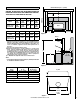
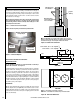
Firebox Brick Layout Viewed From the Front Brick Installation 24 E Figure 2 CAUTION: Wear gloves during brick installation in case of sharp edges behind the fireplace insert. Note: Installation of the baffle boards and baffle blankets are easier when you can still access the flue outlet, (before connecting the flue vent). Be sure the baffle blankets are placed flat on the baffle boards so as not to block exhaust flow to the flue.
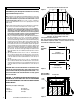
Maximum Mantel Depth = 9” (229mm) Required Clearances COMBUSTIBLE MANTEL WARNING: BE ABSOLUTELY SURE THE DISTANCE BETWEEN THE HEATER AND THE SURFACE OF ANY COMBUSTIBLE CONSTRUCTION IS NOT LESS THAN SHOWN ON THIS PAGE.
Using the r formula: Hearth Protection The hearth and/or floor protection must be a thermally rated non-combustible hearth/floor protector meeting or exceeding a thermal rating of k=.84 or equivalent with a listed thickness of 3/8" (9.5mm) minimum in USA (3/4" - 19mm minimum in Canada). The covering must extend 18” (450mm) in front of the heater and 8” (200mm) to either side (measured from door opening in the USA and measured from the side of the unit in Canada).
FOLLOWING EXAMPLES ARE CALCULATED FOR CANADA REQUIRMENTS Using the k formula: Minimum thickness of = alternate material (TM) k-value (per Inch) of alternate material (kM) x k-value (per inch) of listed material (kL) Specified min. thickness of listed material (TL) TM (inches) = *.84 kM x TL TM (inches) = *.35 *.84 x .75" .312 (inches)= .417 x .75" Answer - The minimum required thickness of the Micore 160 is .
POSITIVE FLUE CONNECTION A full chimney liner is recommended A positive flue connection is providing a seal between the vent pipe or liner and the existing fireplace chimney for the purpose of preventing room air passage to the chimney cavity of the fireplace. There are different approved methods to achieve this. See Direct Connect Positive Flue Connection on this page.
Installation Procedure - Factory-Built Zero Clearance Fireplaces Fireplace and Chimney Requirements This appliance must only be installed in a zero clearance factory-built fireplace using 6” (152mm) stainless steel pipe extending from the insert’s flue into the chimney of the fireplace. For optimum safety and performance we recommend a full length stainless steel liner directly connected to the insert’s flue outlet.
Chimney Liner Installation Remove the existing chimney cap and install a stainless steel liner into the chimney (if a special section has been used or drilled to attach to the insert, it must be the bottom piece). The next piece should be a dripless slip joint, followed by the rest of the chimney liner. Fasten the chimney at the top when it is positioned so that the slip joint will allow the lowest piece to slide up enough to clear the insert during installation.
Starting and Maintaining a Fire Operating Hints 1. Burn only dry, well-seasoned wood for maximum heat output. In some states it is illegal to burn wet wood or anything other than clean, dry wood products. 2. Your fireplace insert is designed to operate with the door closed! Operate only with the door shut tightly at all times except when loading wood and possibly on start up to establish a draft. Never leave the unit unattended while the front door is slightly opened. 3.
BLOWER OPERATION Blower Operation The blower can be operated manually or automatically (blower will turn on when the insert is hot and turn off when the insert is cool). The rocker switch on the control panel allows you to select between manual operation or automatic operation as follows (see Figure 10): MANUAL OPERATION: Turn rocker switch to the manual position (up) and adjust rheostat knob to the desired speed.
Achieving Clean, Long Burns Operating Techniques and Hints Recent developments in wood-burning technology have made wood-burning a cleaner and more convenient way to heat your home. Overall efficiency in a wood-burning appliance is a combination of combustion efficiency and heat transfer efficiency. Whether heating your entire home or just a room or two, your understanding of how to best operate your stove or insert will enhance its overall efficiency and performance.
Maintenance CAUTION Door Hinges: If door hinges need lubricating, use an anti-seize compound (never use oil) available from your Lennox Hearth Products dealer. Door Latch: If your door latch fails to latch tightly and the gasket is in good condition, place a length of pipe (cheater bar) over the inside portion of the door handle and bend slightly toward the door until the proper adjustment is obtained. If the door handle does not close easily, apply high temperature anti-seize to the striker.
Troubleshooting Problem Solution POOR DRAFT: Extend chimney in length or have the chimney realigned to the proper size flue. Oversized chimneys normally have poor drafts. Remember, the fireplace inserts’ draft depend solely on the natural draft of the chimney (See Draft Requirements on Page 4). If your fireplace insert is not drafting properly, your chimney is the problem. All stoves and fireplace inserts are thoroughly tested to ensure proper draft with the correct size chimney flue.
Do’s and Don’t DO NOT: Install or operate this fireplace insert before reading this manual. DO NOT: Close the draft beyond the point at which the flames are completely extinguished. DO NOT: Open the fireplace insert door without fully opening the draft first. DO NOT: Burn driftwood or wood that has been in salt water. This includes some mill ends and scrap lumber that has been floated in salt water on the way to the mill. (This will void your warranty).
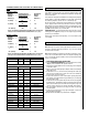
Replacement Parts - Models C210, CA210 AND SWI210 Contact an Lennox Hearth Products dealer to obtain any of these parts. Never use substitute materials. Use of non-approved parts can result in poor performance and safety hazards.
Replacement Parts - Models C210, CA210 AND SWI210 47 33 46 34 45 36 36 35 37 37 44 40 40 38 38 38 38 38 42 38 38 38 41 38 38 41 38 38 39 20 NOTE: DIAGRAMS & ILLUSTRATIONS ARE NOT TO SCALE.
Replacement Parts - Models C210, CA210 AND SWI210 Door Parts 2 1 3 2 1 3 14 4 11 5 8 13 6 4 9 5 7 8 6 7 12 10 Blower Parts 29 15 17 16 19 32 18 NOTE: DIAGRAMS & ILLUSTRATIONS ARE NOT TO SCALE.
Accessories - Models C210, CA210 AND SWI210 Product Reference Information BLOWERS Cat. No. Model Description H7907 WSINS-BLWR-B-SS Ship. Weight Ship. Volume H7908 WSINS-BLWR-G-SS Blower Insert Gold H7909 WSINS-BLWR-N-SS Blower Insert Nickle C210T-B, Insert / Traditional Black Door / Nickel Nameplate 427 lb. 18.30 cu. ft. H7910 WSINS-BLWR-BN-SS Blower Insert Br-nkl H7892 C210A-B, Insert / Arch Black Door / Nickel Nameplate 426 lb. 18.35 cu. ft.
SAFETY / LISTING LABEL - Models C210, CA210 AND SWI210 2011 2012 2013 23
Warranty Your wood appliance is covered by a limited warranty (provided with the appliance). Please read the warranty to be familiar with its coverage. 3. The part number. 4. The description of the part. 5. The quantity required. 6. The installation date of the appliance. Retain this manual. File it with your other documents for future reference. If you encounter any problems or have any questions concerning the installation or application of this system, please contact your dealer.