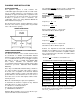
INSTALLATION AND OPERATION MANUAL EPA CERTIFIED CATALYTIC WOOD BURNING FIREPLACE INSERT RETAIN THESE INSTRUCTIONS FOR FUTURE REFERENCE MODEL BV4000C THIS APPLIANCE MUST BE INSTALLED BY A QUALIFIED TECHNICIAN. READ MANUAL THOROUGHLY BEFORE INSTALLATION. P/N 775006M, Rev.
IMPORTANT WARNINGS CAUTION: Read this manual thoroughly before starting installation. For your safety, follow the installation, operation and maintenance instructions exactly without deviation. Failure to follow these instructions may result in a possible fire hazard and will void the warranty. If this appliance is not properly installed, a house fire may result. Contact local building or fire officials about restrictions and installation inspection in your area. 1.
TABLE OF CONTENTS Important Warnings ................................................. 2 CONGRATULATIONS ON THE PURCHASE OF YOUR NEW WOOD BURNING FIREPLACE INSERT MANUFACTURED BY LENNOX HEARTH PRODUCTS. Testing / Listing, EPA, Using this Manual ............... 3 Planning Your Installation......................................
PLANNING YOUR INSTALLATION QUESTIONS TO ASK LOCAL BUILDING OFFICIAL A correct installation is critical and imperative for reducing fire hazards and perilous conditions that can arise when wood burning appliances are improperly installed. The installer must follow all of the manufacturers’ instructions. The installation of a wood burning appliance must conform to local codes and applicable state and federal requirements. Familiarity with these requirements before installation is essential.
PLANNING YOUR INSTALLATION FLOOR PROTECTION This appliance requires a heat resistant noncombustible approved fireplace hearth or hearth extension. If a hearth extension is used it must be a 3/8" (minimum) UL approved hearth pad or equivalent. If the floor protection is to be stone, tile, brick, etc., it must be mortared or grouted to form a continuous noncombustible surface (See Using Alternate Material As Floor Protector on this page).
PLANNING YOUR INSTALLATION CHIMNEY INSPECTION The existing fireplace should be inspected by a local fire marshal or qualified installer for adequate serviceability prior to installing this appliance. Factory built fireplace: If any portion of the chimney system shows signs of structural or mechanical weaknesses, such as: cracks, leaky joints, corroded or warped surfaces. Look for obvious bulges in the lining, which may indicate the need to replace that section (use a bright flashlight.
PLANNING YOUR INSTALLATION FACTORY BUILT FIREPLACES This appliance is approved for installation into a listed factory built solid fuel burning fireplace. The fireplace firebox must accept the insert without modification other than removing bolted or screwed together pieces such as smoke shelf/deflectors, ash lips, screen or door tracks and damper assemblies, that must be reinstalled to restore the fireplace to its original operating condition if the insert is removed and not replaced.
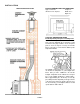
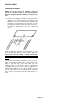
INSTALLATION FIREPLACE INSTALLATION BV4000C MINIMUM FIREPLACE DIMENSIONS Approx. minimum Height: 21” dimensions into fireplace Width: 22 ½” Depth: 16” CATALYTIC TEMPERATURE PROBE Install temperature probe prior to installing insert. To install the Catalytic Temperature Probe locate the plug on the top, right-hand side of the bypass control rod. Remove the plug, install the sleeve, and place probe in sleeve.
INSTALLATION INSTALLATION STEPS 1. Remove all ashes from the fireplace. 2. Remove all materials inside the insert and set them aside. 3. Remove the three-piece surround assembly (face shield) and attach insulation material provided using a nonflammable adhesive (i.e. RTV Silicone, rated 570° F). 4. Use a large piece of cardboard or other protective material and place it in front of the fireplace to protect floor or carpet during installation. 5. Remove the insert from its wood pallet by removing the screws.
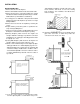
INSTALLATION SURROUND ASSEMBLY NOTE: Do not face seal over chimney cooling air system on superior brand or any brand fireplace which is designed with the chimney cooling air system. 13. Pull the insert slightly forward to its desired position; attach the face shield using the surround clips and hardware as shown. The fiberglass insulation strips should be secured along the top and sides (step 3). Assemble the gold-tone trim using the 2 inside corner brackets. Attach trim to the face shield and stove.
INSTALLATION POSITIVE FLUE CONNECTION FOR MASONRY FIREPLACE A Professional should inspect chimney prior to installation to determine if any repairs are necessary or if a chimney reline is necessary. This can be achieved by using a filler plate. A filler plate can be made by making a cardboard pattern to fit the fireplace throat. Lay the pattern on 22 gage steel, add 2 inches to each side, and cut. Snip corners and bend front lip up and sides and back down. Cut an opening for the flue.
PROCUCT FEATURES AND CONTROLS ASH DRAWER The large ash drawer located below the fuel door is designed to make cleaning easier by containing the ashes in a removable drawer. PRIMARY AIR CONTROL The primary combustion air delivery is controlled by the primary air control draft module (The control handle is located above the fuel door). The heat output can be controlled by sliding the handle to a higher or lower heat output setting (see following illustrations).
CARE AND OPERATION FUEL DOOR CAUTION: When opening the door, do not extend it beyond its normal travel. Overextending the door to a further open position can put excessive stress on hinge area of door and hinge pins and may result in breakage. PRIMARY AIR CONTROL This appliance is equipped with a control for the combustion air, located above the fuel door. Sliding the control to the right increases the burn rate, to the left decreases the burn rate.
CARE AND OPERATION BREAK-IN PERIOD Your fireplace insert finish is a high temperature paint that requires time and temperature to completely cure. We recommend that you ventilate the house during the initial burns. The paint emits non-toxic odors during this process. KEEP YOUR HOUSE WELL VENTILATED DURING THE CURING PROCESS TO PREVENT ACTIVATION OF YOUR HOME SMOKE DETECTOR. The paint manufacturer recommends three burn cycles to cure the paint. The first two burns should be low heat, approximately 250°F.
CARE AND OPERATION BLOWER SYSTEM The Blower System consists of a ON/OFF rocker switch, a variable speed blower speed control switch (rheostat), a thermally activated switch (fan disc) and 2 axial blowers. When starting a fire, leave the blower system off until the insert is thoroughly heated (approx. 30 minutes after start up).
CARE AND OPERATION BYPASS DAMPER CONTROL The operating handle of your bypass damper control is located on the front of the stove flue collar. By moving the bypass damper control, the operator can route the fire either through the catalytic combustor (pushed in) or directly up the flue (pulled out). When starting a fire or refueling, the bypass damper control should be pulled out. Once the fire is established, it should be pushed in.
MAINTENANCE BURN RECOMMENDED FUEL This appliance is approved for use with natural dry wood only. Burning materials other than natural wood will shorten the life of the catalytic combustor. Do not burn particleboard or pressed logs using bonding agents as they can produce conditions which will deteriorate metal or damage the catalyst. Green or uncured wood does not work well as fuel, and can cause increased creosote buildups and plugging of the catalytic combustor.
MAINTENANCE DOOR/GLASS GASKET AND ASH DUMP GASKET A 3/4" spun fiberglass gasket provides the seal around the fuel door and a flat spun fiberglass rope gasket (1/8” x 1”) provides the seal around the glass. A cerawool pad (4 1/4” x 4 1/4” x 1/2”) provides the seal for the ash dump cover. Should these gaskets become frayed or damaged, they should be replaced with the same size and type as the original gasket. Contact your dealer for ordering.
MAINTENANCE CATALYTIC COMBUSTOR This appliance has been designed with a catalytic combustor, which will improve its overall performance. Removing the combustor assembly for cleaning and reinstallation is simple and convenient. Cleaning the combustor helps reduce buildup of ash and retarding chemicals. To clean the combustor, a soft brush, vacuum cleaner, or pipe cleaner may be used. Cleaning the combustor once a year, preferably when your flue system is serviced, is sufficient for most users.
TROUBLESHOOTING * SMOKES OUT FUEL DOOR WHEN OPEN 1. The primary air control is closed. 2. The chimney is too cool. Set the primary air control on "HIGH" with the bypass damper control "OPEN" for a few minutes before opening the fuel door. 3. Excess creosote will not only restrict your draft but it will create a risk of a creosote fire. Strictly adhere to maintenance requirements as outlined in this manual.
TROUBLESHOOTING CATALYST PLUGGING 1. Burning materials that produce a lot of char and fly ash. Do not burn materials such as garbage, gift wrap, cardboard, etc. 2. Burning wet pitchy woods or burning large loads of small diameter wood with the combustor in the operation position (without light-off taking place). Burn proper fuel only. Do not close bypass until temperatures are high enough to initiate light off.
SPECIFICATIONS - Model BV4000C Note: Dimensions shown are approximations only (+/- ¼”) Approx. sq. ft heat capacity up to ~ 2000 Sq. Ft. Maximum log length 18" Flue size 6" Width w/standard surround 42" Width at fireplace opening 22.5" Width at rear of firebox 22.5" Depth into Fireplace 16" Depth (overall) 25" Height 21" Height w/standard surround 32" Back of Stove to Center of Flue 5 1/2" Approx. burn time 8 - 10 hours Fuel capacity 70 lbs. (approx.) Firebox size (cubic feet) 2.4 c.
REPLACEMENT PARTS LIST – Model BV4000C 11573 DOOR PARTS Part/ Description Notes Catalog # G6000 Door assembly, cast black 410-25-3 Blower, axial 13 1/4" (J239- Includes propeller 5116) .
COMPONENT DIAGRAMS – Model BV4000C CATALYTIC/DAMPER COMPONENTS PRIMARY AIR CONTROL DRAFT MODULE (PART/CATALOG #11493) HANDLE ASSEMBLY (PART/CATALOG #10300) DOOR ASSEMBLY (PART/CATALOG #G3000) DAMPER ASSEMBLY PAGE 24
OPTIONAL ACCESSORIES - Model BV4000C Accessories Catalog # Description (Model) Notes 14M73 Cord change over kit (CCOK-4000) 14M72 Gold Door Kit (DK100-G) 70K99 Touch-up spray paint kit, black 12 oz Spray (TSPK-B) Can (SKS-4000) Surround Kit, Small, 28” ht. X 36” wd. (SKL-4000) Surround Kit, Small, 32” ht. X 48” wd. Offset adapter, 6” to 6” diameter (OA4000-66) 14M70 14M71 14M76 OFFSET ADAPTER Installations requiring offsets can be handled using an offset adapter (it aligns starter pipe with flue).
SAFETY LISTING LABEL / EPA LABEL PAGE 26
SERVICE AND MAINTENANCE LOG Service Date Service Technician Service Description PAGE 27
1110 West Taft Avenue Orange, CA 92865