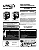
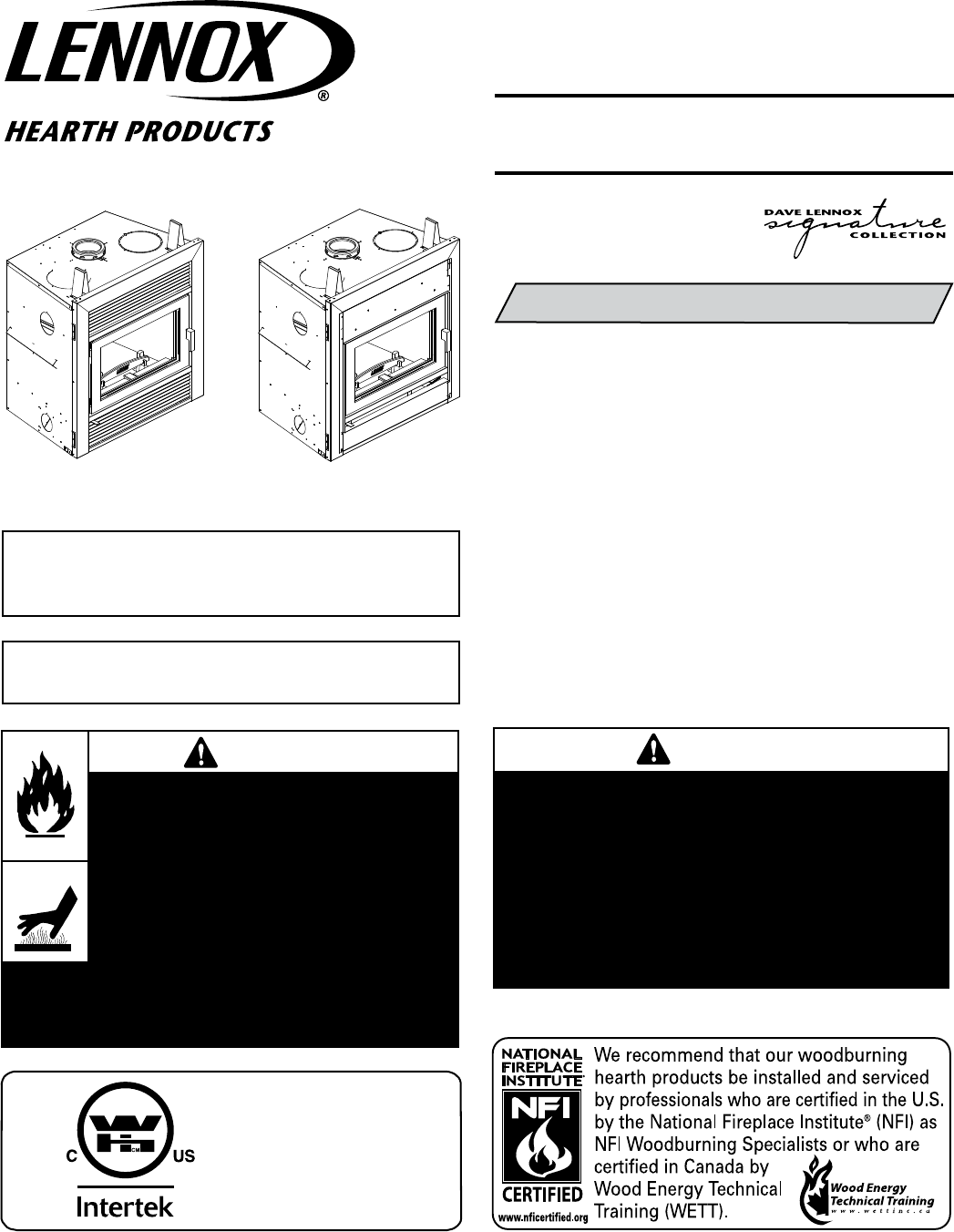
INSTALLATION AND OPERATION INSTRUCTIONS Brentwood™ LV EPA Wood-Burning Fireplaces P/N 506023-13 REV. A 02/2011 TM MODEL Brentwood LV This installation manual will enable you to obtain a safe, efficient and dependable installation of your fireplace system. Please read and understand these instructions before beginning your installation. Shown with louver kit installed Shown with clean face kit installed THIS UNIT REQUIRES THE INSTALLATION OF A FINISHING KIT.
IMPORTANT! GENERAL SAFETY PRECAUTIONS. READ AND UNDERSTAND THESE SAFETY RULES BEFORE YOUR FIRST FIRE. WARNING THE FIREPLACE MUST BE OPERATED WITH THE DOOR FULLY OPENED OR DOOR FULLY CLOSED. IF THE DOORS ARE LEFT PARTLY OPENED, GAS AND FLAME MAY BE DRAWN OUT OF THE FIREPLACE OPENING, CREATING RISKS OF BOTH FIRE AND SMOKE. WARNING NEVER use gasoline, gasolinetype lantern fuel, kerosene, charcoal lighter fluid, naphtha, engine oil or similar liquids to start or “freshen up” a fire in this fireplace.
Congratulations! Parts Required When you purchased your new wood fireplace, you joined the ranks of thousands of individuals whose answer to their home heating needs reflects their concern for aesthetics, efficiency and our environment. We extend our continued support to help you achieve the maximum benefit and enjoyment available from your new wood fireplace.
OPERATING THE fireplace Fuel USE SOLID NATURAL WOOD FUEL ONLY. The Brentwood™ LV fireplace is designed to work best when fueled with dry seasoned natural wood only. Hardwoods are preferred to softwoods since the energy content of wood is relative to its density. Hardwoods will result in a longer burning fire and less frequent refueling. A moisture content of 15% to 20% (seasoned) is recommended.
Use caution when firing with the combustion air control wide open. Only burn cord wood in this manner. Small dry pieces of softwood and construction scraps will burn very intensely using this method and may damage the firebox. Medium Combustion This is the recommended mode of operating the Brentwood™ LV fireplace and should be the one normally used since it will deposit the least amount of creosote on the glass and in the chimney.
MAINTAINING YOUR BRENTWOOD™ LV FIREPLACE Top Baffle Removal Prior to Cleaning The Chimney Creosote - Formation and Need for Removal When wood is burned slowly, it produces tar and other organic vapors, which combine with expelled moisture to form creosote. The creosote vapors condense in the relatively cool chimney flue of a slow-burning fire. Before starting to clean your chimney, we recommend that you remove the top baffle to avoid creosote dust collection at the top of the baffle.
REFRACTORY REPLACEMENT The intense heat of the fire will normally cause hairline cracks in the refractory. These cracks can be minimized by proper curing as described in “First Fires”. They will not normally diminish the effectiveness of the refractory. If large cracks develop, then the refractory should be replaced. To replace the refractory bricks, follow these steps: 1. Remove the front refractories 2. Remove the bottom refractory 3. Remove the left side refractory 4. Remove the right side refractory 5.
Glass Care Gasket Replacement Glass Replacement The glass used for the Brentwood™ LV fireplace is a high temperature ceramic glass (1,400° F / 760° C). If the glass breaks, it must be replaced with an identical ceramic glass. Tempered glass or ordinary glass will not withstand the high temperatures of the Brentwood LV fireplace. Replacement glass should be purchased from a Lennox Hearth Products dealer (see “Replacement Parts”, Page 28). DO NOT OPERATE THE UNIT WITH CRACKED OR BROKEN GLASS.
INSTALLING THE FINISHING KITS The Brentwood™ LV requires the installation of a finishing kit. Two options are available: 1. Louver kit (part number: LOUVRECF) OR 2. Clean face kit (part number: CAPPINGCF) Installing The Louver Kit The louver kit includes two identical louver assemblies. The louvers must be oriented so the angular parts of the grills are towards the front and the bottom and the cotter pins are at the bottom. Insert the top of the louver rods in the top trims holes.
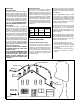
Framing, Facing And Mantel The construction of the framing, facing, and mantel must be in accordance with the standards and the following illustrations (Figures 9, 10 and 11): A. Frame the fireplace using 2” x 3” or heavier lumber. B. WARNING: Combustible materials cannot be used in the space directly above the fireplace, except for the studs above the facade that support the facing and mantel. This area must remain empty for a height of 6’8” (2,032 mm) measured from the base of the appliance. C.
Back Wall of Chase/Enclosure Including Finising Materials if any Combustion Air Kit Corner Installation OUTSIDE CHASE C L* 21-1/2” D J F G H K A FRAMING DIMENSIONS A 36-1/4” 921 mm B 40-3/4” 1035 mm C 28-1/8” 714 mm D 13-1/4 337 mm E 76-3/4” 1950 mm F 38-3/8” 975 mm G *25” 635 mm H 24-1/2” 622 mm J 54-1/4” 1378 mm K 8” 203 mm L 1” 25 mm 20-3/8” Rough Framing Face (Unfinished Shown) * Zero Clearance From Back Spacer to Wall Combustible materials can NOT be used
Insulate Joists Same As Ceiling Insulated Chase Construction Storm Collar Roof Support Flashing Attic Radiation Shield Draft Stops Floor Ceiling Wall NOTE: It is recommended that the chase walls and floor be insulated in the same manner, using the same insulation, as the rest of the building, below the attic. Firestop CTDT Termination • Must have the same firestopping Note: Nonresistance as adjacent wall. Combustible • Must have the Chase same insulation as adjacent ceiling.
Facing The facing installation method depends on your finishing kit choice. 1. Facing with the louver kit - The 2x3 framing must offset to the back by a distance equivalent to the thickness of your facing material so the surface of the facing be aligned with the fireplace face. Combustible materials must be aligned with the fireplace face and can not overlay on the fireplace front (black steel face of the fireplace) (see Figures 14 and 15).
HOT AIR DUCTING INSTALLATION Different hot air ducting systems can be installed with the Brentwood™ LV fireplace: - Gravity kit - Forced air kit Gravity Kit The gravity kit is designed for double hot air outlets and includes: (See Figures 20 and 21) - 2 telescopic lengths 8” I.D. - 2 90º elbows 8” I.D. - 2 hot air outlet kits (grill and frames) - 2 adaptors WARNING: The outlet grills should not be installed facing upward through a floor. Danger of burns can result if grills in floor are stepped on.
The duct system must be installed respecting the following: 1. Remove the plates closing up the 8” dia. holes on top of the fireplace. Then, cut the insulation and remove the plate under the insulation in order to obtain two 8” dia. openings. Fix the adaptors on the fireplace openings by turning clockwise (Figure 20). 2. Maintain at least a 2” (50 mm) clearance between the ducts and any combustible material; the required hole size is 13” x 13” (330 mm x 330 mm).
OUTSIDE AIR KIT - REQUIRED (Included w/fireplace) During operation, the fireplace requires fresh air for combustion and draws air out of the house. It may starve other fuel burning appliances such as gas or oil furnaces. As well, exhaust blowers may compete for air, causing negative pressure in the house, resulting in smoke entering the house from the fireplace. This situation is aggravated in modern airtight houses. To overcome this problem, we strongly recommend that you install an outside air assembly.
THE CHIMNEY system Chimney Installation Notes 1. Always install an interior chimney as it will provide better performance. In areas with continuous temperatures below 0° F (- 18° C), the use of an exterior chimney increases the likelihood of operating problems such as low draft, high rate of creosoting, and poor start-up characteristics. Exterior chimneys are also prone to down drafting and flow reversal.
CHIMNEY INSTALLATION INSTRUCTIONS 1. Cut and frame the holes in the ceiling, floor and roof where the chimney will pass (see Figure 28). Use a plumb-bob to line up the center of the holes. The sizes are indicated in Table 2 for the floor and ceiling holes and Table 3 (Page 19) for the roof holes.
Figure 31 After reaching the location requiring the elbow, proceed as follows: AC Air Cooled Chimney Chimney ASHT / HT6103+ / S-2100+ / HT6000+ Chimneys Collar Spacer (built into flashing) Flashing Figure 32 Figure 31 Roof Down Slope Hole Size SLOPE ASHT / HT6103+ S-2100+ / HT6000+ AC Roof Pitch 6” 6” 6” 0* 12-3/8” (314 mm) 14-1/8” (359 mm) 15” (380 mm) 2/12 12-9/16” (319 mm) 14-3/8” (365 mm) 15 3/8” (390 mm) 4/12 13” (330 mm) 14-7/8” (378 mm) 16 1/8” (410 mm) 6/12 13-7/8” (352
Offset Dimensions B Total Height A Chimney 6” Elbow 15º Secure Temp ASHT 30º Nova Temp HT6103+ 45º Chimney 6” 18” 24” 36” 48” 8” & 48” 12” & 48” 18” & 48” 24” & 48” 36” & 48” 48” & 48” A 3-5/16” (84mm) 4-5/16” (110mm) 5-7/8” (149mm) 7-7/16” (189mm) 10-1/2” (267mm) 13-5/8” (346mm) 15-3/8” (391mm) 16-7/16” (418mm) 18” (457mm) 19-1/2” (495mm) 22-5/8” (575mm) 25-3/4” (654mm) B 15-11/16” (398mm) 19-9/16” (497mm) 25-3/8” (645mm) 31-3/16” (792mm) 42-3/4” (1086mm) 54-3/8” (138
ANGLED WALL RADIATION SHIELD (RSM+ and RSMI30) When traversing a combustible wall with the chimney at a 30º or 45º angle, an angled firestop or wall radiation shield must be installed. Only one is required. Support ACRS Straps Straps Chimney AC Starter Section Note: 45º angle for Canada only (RSMI45) In cold climate locations (climates where temperatures will fall below 32° F / 0° C), we recommend that you use the insulated wall radiation shield since it will maintain the home’s thermal barrier.
CHIMNEY SUPPORT INSTALLATION Universal Roof Support 18” (460 mm) When installing a support, slightly lift the chimney system so the weight will lie on the support, not on the fireplace to reduce expansion noises. This support has three possible uses: 1. For ASHT / HT6103+ and S-2100+ / HT6000+, it must be used on a roof to support the chimney. 2. It may be used on a floor, ceiling or roof above an offset to support the chimney above the offset. 3.
INSTALLATION INSTRUCTIONS FOR MASONRY APPLICATION Follow these steps: WARNING: Before starting the installation, the masonry chimney must be inspected by a qualified chimney sweep. 1- Position the fireplace in its location. Temporarily install the ASHT elbow on the top of the fireplace and, using a level, mark with an oval the location where the flue liner will enter the masonry chimney. 2- In the middle of the oval, drill a hole in the masonry chimney at 30º.
Optional installation accessories Installation Accessories Description Fireplace Kits Cat./Part No.
Chimney - PARTS AND COMPONENTS LISTs Fireplace Model Brentwood LV - Approved Venting Components manufactured by Security Chimneys International only. Secure Temp ASHT 1” High Temp. Insulated Stainless Steel Chimney 6” I.D and 8” O.D., Double-Wall Stainl. Steel, Listed to CAN/UCL-S604 and UL-103HT Description Part/Cat. No. Lengths and Misc. Chimney Components 8” length, 6” Dia., 6L8 6L8 12” length, 6” Dia., 6L12 6L12 18” length, 6” Dia., 6L18 6L18 24” length, 6” Dia.
Chimney - PARTS AND COMPONENTS LISTs (AC) Air-Cooled Chimney System* TUBINOX LL Chimney Lining System 6” I.D. and 11” O.D. Air Cooled, Stainl. Steel inner and zinc coated steel exterior AC Starter Adaptors * AC Chimney is NOT recommended at elevations above 4,000 feet or in cold climates (climates where temperatures will fall below 32° F / 0° C). Cat./Part No.
SPECIFICATIONS CLEARANCE TO COMBUSTIBLES Cat. No. Model H8295 Brentwood™ LV The following clearances meet the minimum requirements for a safe installation: Side wall: 24” (610 mm) measured from the fireplace side. Ceiling: Product Reference Information Weight 385 lbs Height 36” 6’ 8” (2,032 mm) measured from the base of the fireplace. Fireplace enclosure: Bottom: 0” Side: 0” to spacer Back: 0” to spacer Top: Do not fill the space above the fireplace with any material (Except the wood framing.
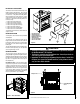
REPLACEMENT PARTS - Brentwood™ LV Brentwood™ LV Item # Description Cat./Part No.
REPLACEMENT PARTS - Brentwood™ LV 17 18 12 15 8 20 16 1 10 14 30 19 22 23 24 21 11 2 3 20 25 26 5 31 13 PA I N T 6 4 7 28 29 NOTE: DIAGRAMS & ILLUSTRATIONS ARE NOT TO SCALE.
Warranty Your fireplace is covered by a limited warranty. Please read the warranty to be familiar with its coverage. Retain this manual. File it with your other documents for future reference. Product reference information We recommend that you record the following important information about your fireplace. Please contact your Lennox Hearth Products dealer for any questions or concerns. For the number of your nearest Lennox Hearth Products dealer, please call 1-800-9-LENNOX.