HOMEOWNER'S CARE AND OPERATION INSTRUCTIONS B-VENT SEE-THROUGH MERIT® PLUS SERIES B-VENT GAS FIREPLACES P/N 875,024M REV. NC 04/2005 MODELS Millivolt Models Electronic Models MPB35ST-NM MPB35ST-PM MPB35ST-NE A French manual is available upon request. Order P/N 875,024CF WARNING: IF THE INFORMATION IN THIS MANUAL IS NOT FOLLOWED EXACTLY, A FIRE OR EXPLOSION MAY RESULT CAUSING PROPERTY DAMAGE, PERSONAL INJURY OR LOSS OF LIFE.
CONGRATULATIONS! In selecting this LENNOX B-Vent Gas Appliance you have chosen the finest and most dependable fireplace to be found anywhere. Its a beautiful, prestigious alternative to a wood burning fireplace. Welcome to a Family of tens of thousands of satisfied LENNOX Fireplace Owners. Please carefully read and follow all of the instructions found in this manual. Please pay special attention to the safety instructions provided in this manual.
Test gauge connections are provided on the front of the millivolt gas control valve, identified IN for the inlet and OUT for the manifold side (see Figurex 2 on Pagex 4 ). A 1/8" NPT Test gauge connection is provided at the inlet and outlet side of the electronic gas control valve (see Figurex 3 on Pagex 5).
WARNING WARNING Carbon monoxide poisoning: early signs of carbon monoxide poisoning are similar to the flu with headaches, dizziness and/or nausea. If you have these signs, obtain fresh air immediately. Turn off the gas supply to the appliance and have it serviced by a qualified professional, as it may not be operating correctly. WARNING Any safety guard or screen removed for servicing the appliance must be replaced prior to operating the appliance.
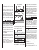
Millivolt appliances are fitted with an OFF/ON Rocker Switch located behind the control compartment access panel, below the appliance front glass enclosure panel (see Figure 1 for location). Once the pilot is lit, the OFF/ON rocker switch will control the appliance OFF/ON burner operation. To operate: Toggle the switch between its ON and OFF positions.
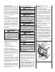
Outside Combustion Air Controls Many appliances are equipped, when installed, with an outside (make-up air) vent system that is designed to provide the appliance with outside make-up air for combustion when in operation. The outside air control lever for the outside air system is standard on all appliances but should not be operated if the complete system is not installed. Refer to Figure 5.
Cleaning Logs And Burner Carefully remove the logs (use care when handling the fiber logs, as they become quite fragile after curing). Vacuum out any foreign matter (lint, carbon, etc.) on the burner. Ensure the burner ports are “open.” Remove any carbon deposits from the under side of the logs using a vacuum cleaner, or a soft bristled brush (i.e. paint brush). Note: Improper positioning of logs can create carbon build-up and will alter the performance of the appliance.
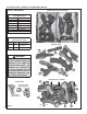
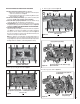
RE-INSTALLING GRATE, VERMICULITE, GLOWING EMBERS AND LOGS Bottom View of Logs (in packaging) LOG SET - IDENTIFICATION LOG SET Catalog Number H3210 * Item Description A Log, Center B Log, Left Rear C Log, Left Front D Log, Right Rear E Log, Top Center F Log, Front Center C A B F * Item "letters" above correspond to photos on right D E REFERENCE Firebox Accessories / Parts Cat. No. Model No. 88L53 FGE 42363 Description Bag of Glowing Embers (1 oz.
READ LOG WARNINGS ON PAGE 9 BEFORE PROCEEDING 1. Remove front glass enclosure panel from appliance. a. Open Control Compartment Access Panel (see Control Compartment Access Instructions on Page 4. b. Remove the glass panel enclosure (see Removing Glass Enclosure Panel instructions on Page 9. 2. Remove the following from firebox; log set, embers (rockwool) and vermiculite. Handle logs carefully to prevent breakage. 3.
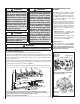
. Place Log (E) as shown in Figure 13. Position round end of log (E) against the notch of log (D) here. Two charred spots face the front E D C Position Small End of Log (E) on The Notch of Log (C) Here (Valve Access Side) Figure 13 11. Place Log (F) as shown in Figure 14. Log (F) sits in front of the grate (Valve Access Side) F Figure 14 WARNING This appliance is not designed to burn wood. Any attempt to do so could cause irreparable damage to appliance and prove hazardous to your safety.
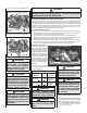
2. Light appliance (follow lighting procedure on Decrease Shutter Opening lighting label in control compartment or see Main Burner Factory Air Shutter Note - Burners are In This Direction homeowners manual). Opening Setting - All Models omitted in this 3. Allow the burner to operate for at least 15 minview for clarity. Model Natural Propane utes while observing the flame continuously to Gas Gas ensure that the proper flame appearance has been achieved (see Figure 15).
TROUBLESHOOTING Note: Before troubleshooting the gas control system, Ensure external gas shut off valve, located at gas supply inlet, (and wall switch, iff applicable), is in the “ON” position. Important: Valve system troubleshooting should only be accomplished by a qualified service technician. TROUBLESHOOTING GUIDE - MILLIVOLT GAS CONTROL SYSTEM SYMPTOM POSSIBLE CAUSES 1. Spark igniter will not light pilot after repeated triggering of igniter button. 2.
TROUBLESHOOTING PROCEDURE - ELECTRONIC IGNITION SYSTEM START CHECK • Turn Off Gas Supply. • Ensure Valve Switch Is In ON Position. • Disconnect Control Harness. • Set Thermostat To Call For Heat. • Check for proper voltage at control harness (see insert A). Voltage NO 2 should be 24V between thermostat or pressure switch and 24V common and 24V hot.
1. If any of the original wire as supplied must be replaced, 1. it must be replaced with Type AWM 105°C – 18 GA. wire. 2. 120V, 60Hz – Less than 3 amps. *ON/OFF Switch (Integral with Gas Valve) *Leave the ON/OFF switch, which is integral with the gas valve, in the ON position. BK PILOT ASSEMBLY 120 VAC. R BL G MILLIVOLT PILOT ASSEMBLY White Wire To Opposite Side Junction Box Igniter Rod W B G Transf. 120 V. Hot side of Outlet Thermocouple 3/8" Min.
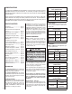
ACCESSORY COMPONENTS Product Reference Information Cat. No. Model Ship. Weight Ship. Volumn H3201 MPD35ST-NM 220 lbs 46W x 26D x 43H (30 cu.ft.) H3202 MPD35ST-PM 220 lbs 46W x 26D x 43H (30 cu.ft.) H3203 MPD35ST-NE 220 lbs 46W x 26D x 43H (30 cu.ft.) 3 Piece Trim Kit Bag of Glowing Embers Bag of Volcanic Stone Replacement ember materials or volcanic stone are available for use with these appliances. Order kits as part of the periodic maintenance of the appliance.
ACCESSORY COMPONENTS Arch Design Arch Pane Design 35" Screen Heat Guard Kit Clean Face Charcoal Radiant Panel Kits Square Design Square Pane Design Cat. No. Model No. 88L36 RAD35C-2 Description Clean Face Panel Kit (ref. Form # 504,223M) Cat. No. 26M48 Model No. Description HG35M 35" Screen Heat Guard Kit (ref.
ACCESSORY COMPONENTS 2-Piece Louver Kits * 35" Eyebrow Hood Kits Cat. No. * 35" Arch Door Kits Cat. No. Model No. Description 26M43 ADK35CMPB Arch Door, Polished Brass 26M44 ADK35CMBS Arch Door, Brushed Stainless Model No. Description 96K67 EB35PB Hood Kit, Polished Brass 88L49 EB35BS Hood Kit, Brushed Stainless * These hood kits replace the standard hood that comes with these fireplaces. Cat. No. Model No. Description 96L05 2LVR35PB 2 Pc.
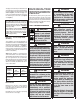
LIGHTING INSTRUCTIONS – MILLIVOLT GAS VALVE FOR YOUR SAFETY READ BEFORE LIGHTING WARNING: IF YOU DO NOT FOLLOW THESE INSTRUCTIONS EXACTLY, A FIRE OR EXPLOSION MAY RESULT CAUSING PROPERTY DAMAGE, PERSONAL INJURY OR LOSS OF LIFE. A. This appliance has a pilot which must be lit with a piezo igniter. When lighting the pilot, follow these instructions exactly. • Do not use any phone in your building. • Immediately call your gas supplier from a neighbor’s phone.
LIGHTING INSTRUCTIONS — ELECTRONIC FOR YOUR SAFETY READ BEFORE LIGHTING WARNING: IF YOU DO NOT FOLLOW THESE INSTRUCTIONS EXACTLY, A FIRE OR EXPLOSION MAY RESULT CAUSING PROPERTY DAMAGE, PERSONAL INJURY OR LOSS OF LIFE. A. When lighting the appliance, follow these instructions exactly. B. BEFORE OPERATING smell all around the appliance area for gas. Be sure to smell next to the floor because some gas is heavier than air and will settle on the floor.
REPLACEMENT PARTS - MPB35ST Item Part/Cat. Qty Description Item Where Used Part/Cat. Qty Description SIT Millivolt Only 1 H3357 1 Gas Train Assembly, NG, MV MPB35ST-NM 1 H3355 1 Gas Train Assembly, LP, MV MPB35ST-PM 14 H3210 1 Log Set All All All 15 LB-92449B 2 Louver Assembly, Upper Charcoal MPB35ST-NE 16 LB-92652B 1 Louver Assembly, Lower, Charcoal (valve access side) MPB35ST-NE & MPB35ST-PE 17 H3359 1 Louver Assembly, Lower, Char.