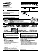
CARE AND OPERATION INSTRUCTIONS MPB35ST B-Vent See-Through Gas Fireplaces P/N 875024M Rev. D 01/2011 MODELS This manual is part of a set of two supporting this product. Refer to P/N 850023M for Installation Instructions. Ce manuel est disponible en francais, simplement en faire la demande. Numéro de la pièce 875024CF. WHAT'S INSIDE Table of Contents . . . . . . . . . . . . . . . . . . . . . . . . . . . . . . . . . . . . . Safety and Your Fireplace . . . . . . . . . . . . . . . . . . . . . . . . . . . .
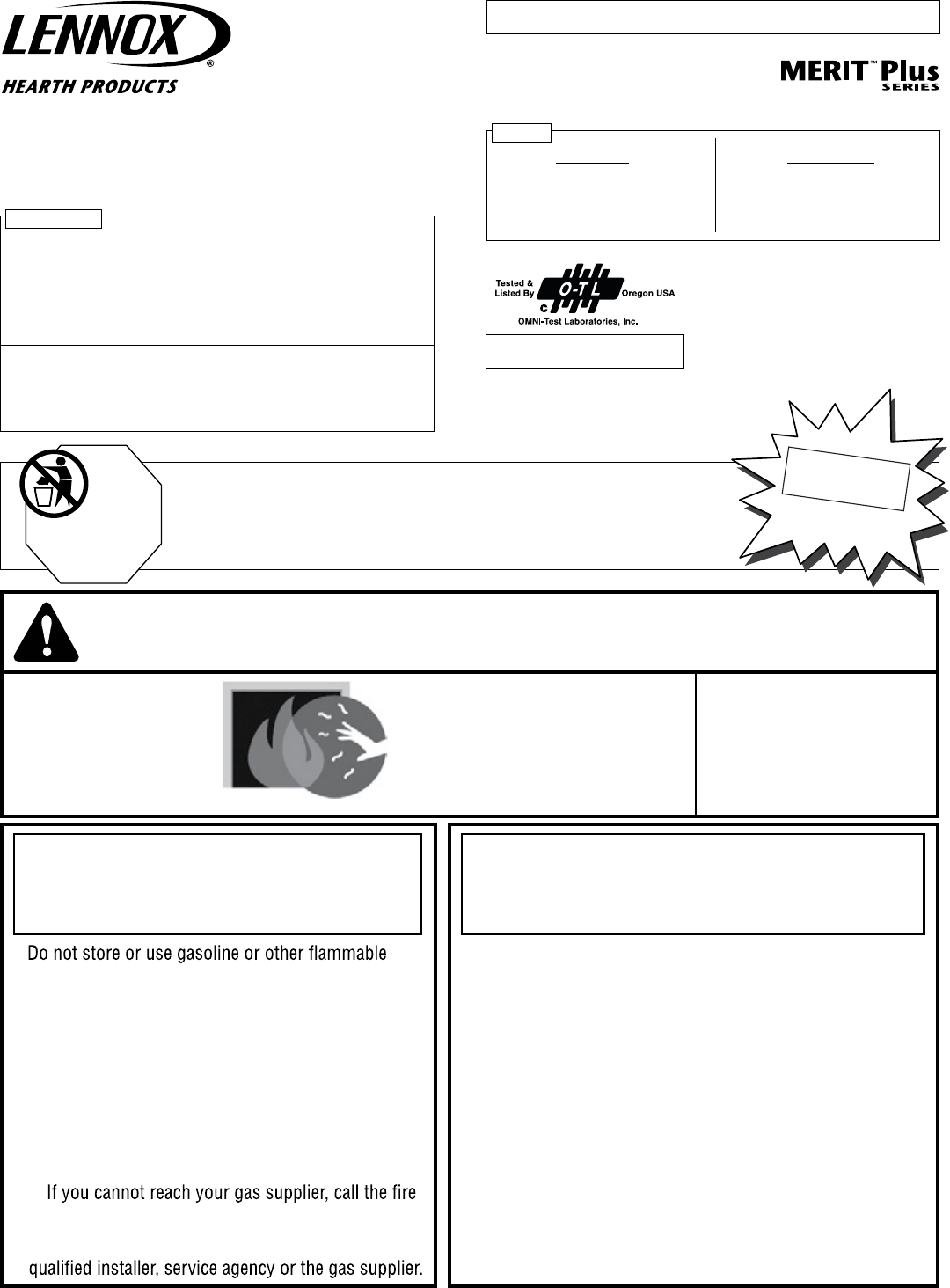
Thank you for your purchase. We appreciate your business! Please carefully read and follow all instructions in this manual. Pay special attention to all warnings and safety information. Following these safety, care, and operation instructions will help ensure many years of dependable and enjoyable service from your fireplace. • FREE SAFETY GUARD OFFER • The Lennox® SAFETY GUARD protects against severe burns and injuries by preventing direct contact with the front glass surface of your fireplace.
[FRENCH] La sécurité et votre foyer Toutes les parties de votre foyer Lennox Hearth Products deviennent EXTRÊMEMENT CHAUDES ! Afin d'éviter de vous brûler gravement ou de vous blesser, installez une grille ou une barrière physique pour empêcher tout contact direct avec la vitre. Pour commander un PANNEAU DE PROTECTION Lennox® GRATUIT pour votre foyer, consultez les détails dans la partie gauche.
Important Safety Information L'information de sûreté importante 1. WARNING: Do not operate appliance with the glass front removed, cracked or broken. Replacement of the glass should be done by a licensed or qualified service person . 1. AVERTISSEMENT. Ne pas utiliser l’appareil si le panneau frontal en verre n’est pas en place, est craqué ou brisé. Confiez le remplacement du panneau à un technicien agréé 2. Do not use this appliance if any part has been under water.
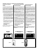
HOMEOWNER’S INSTRUCTIONS - ATTACHING SAFETY-IN-OPERATION WARNINGS Attaching Safety-in-Operation Warnings Apposition des mises en garde relatives à la sécurité d’utilisation Colocación de advertencias de seguridad en operación Your fireplace has been furnished with safety instruction labels that are to be affixed to the operation and control point of the fireplace.
General Information The Millivolt appliances have a millivolt gas control valve with piezo ignition system. The Electronic appliances have an electronic intermittent pilot ignition system. External electrical power is required to operate these units. These appliances comply with National Safety Standards and are tested and listed by OmniTest Laboratories (Report No. 116-F-27-5) to ANSI Z21.500 (in Canada, CSA 2.22), and CAN/ CGA-2.17-M91 in both USA and Canada, as vented gas fireplaces.
Millivolt Models - BTU Input Millivolt models come standard with the manually-modulated gas valve; flame appearance and heat output can be controlled at the gas valve. Input of for these models is shown in Table 1. Input (BTU) Manually-Modulated Gas Valves (millivolt models) Models Fuel Type Input Rate (BTU / HR) MPB35ST-NM-B Nat. Gas 30,000 high 23,000 low MPB35ST-PM-B Propane 28,000 high 22,000 low Table 1 Electronic Models Electronic models have a fixed rate gas valve.
Operation and care of your appliance WARNING Young children should be carefully supervised when they are in the same room as the appliance. Toddlers, young children and others may be susceptible to accidental contact burns. A physical barrier is recommended if there are at risk individuals in the house. To restrict access to a fireplace or stove, install an adjustable safety gate to keep toddlers, young children and other at risk individuals out of the room and away from hot surfaces.
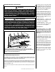
Inlet Pressure Tap Manifold Pressure Tap IN HI/LO Variable Flame Height Adjustment OUT TPTH TP HI TH LO W OF F i t P IL O T ON PIL Main Gas Control Knob OT Pilot Adjustment Screw Gas Inlet TPTH TP TH Main Gas HI/LO Variable Flame Height Control Knob OFF/PILOT/ON Adjustment Terminals TPTH,TP & TH All Millivolt appliances are equipped with a variable gas control valve.
Outside Combustion Air Controls Many appliances are equipped, when installed, with an outside (make-up air) vent system that is designed to provide the appliance with outside make-up air for combustion when in operation. The outside air control lever for the outside air system is standard on all appliances but should not be operated if the complete system is not installed. Refer to Figure 5.
MAINTENANCE (See Maintenance Schedule, Page 26) Refer to the maintenance schedule for maintenance tasks, procedures, frequency and by whom they should be performed. Always verify proper operation of the appliance after servicing. WARNING Turn off gas and electrical power to the fireplace and allow it to cool before cleaning or servicing the appliance. CAUTION: Wear gloves and safety glasses for protection while doing required maintenance. Verify proper operation after servicing.
Front Glass Enclosure Panel, Removal and Installation WARNING • Do not attempt to substitute the materials used on this door, or replace cracked or broken glass. • Handle this glass with extreme care! Glass is susceptible to damage – Do not scratch or handle roughly while reinstalling the glass door frame. • The glass door(s) of this appliance must only be replaced as a complete unit as provided by the manufacturer. Do not attempt to replace broken, cracked or chipped glass separately.
Bottom View of Logs (in packaging) Log set - iDENTIFICATION LOG SET Catalog Number H3210 * Item Description A Log, Center B Log, Left Rear C Log, Left Front D Log, Right Rear E Log, Top Center F Log, Front Center C A B F * Item "letters" above correspond to photos on right REFERENCE Firebox Accessories / Parts Cat. No. Model No. 88L53 FGE H6319 D E Description Bag of Glowing Embers (1 oz.
READ LOG WARNINGS ON PAGE 12 BEFORE PROCEEDING 1. Remove front glass enclosure panel from appliance. a. Open Control Compartment Access Panel (see Control Compartment Access Instructions on Page 8. b. Remove the glass panel enclosure (see Removing Glass Enclosure Panel instructions on Page 12). 2. Remove the following from firebox; log set, embers (rockwool) and vermiculite. Handle logs carefully to prevent breakage. 3.
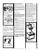
Burner Adjustments 10. Place Log (E) as shown in Figure 13. (QUALIFIED TECHNICIANS ONLY) Position round end of log (E) against the notch of log (D) here. Two charred spots face the front E D C Position Small End of Log (E) on The Notch of Log (C) Here (Valve Access Side) Figure 13 11. Place Log (F) as shown in Figure 14. Log (F) sits in front of the grate Flame Appearance and Sooting Proper flame appearance is a flame which is blue at the base and becomes yellowish-orange in the body of the flame.
Burner Air Shutter Adjustment Procedure WARNINGS • Air shutter adjustment should only be performed by a qualified professional service technician. • Ensure front glass panel are in place and sealed during adjustment. CAUTIONS • Soot will be produced if the air shutter is closed too much. Any damage due to carboning resulting from improperly setting the air shutter is not covered under the warranty. • The air shutter door and nearby appliance surfaces are hot.
Warranty Your gas appliance is covered by a limited twenty year warranty. You will find a copy of the warranty accompanying this manual. Please read the warranty to be familiar with its coverage. Retain this manual. File it with your other documents for future reference. Replacement parts A complete parts list is found at the end of this manual. Use only parts supplied from the manufacturer. With proper care and maintenance, your appliance will provide many years of enjoyment.
Accessory Components Product Reference Information Cat. No. Model Ship. Weight Ship. Volume H7808 MPB35ST-NM-B 220 lbs 46W x 26D x 43H (30 cu.ft.) H7809 MPB35ST-PM-B 220 lbs 46W x 26D x 43H (30 cu.ft.) H7810 MPB35ST-NE-B 220 lbs 46W x 26D x 43H (30 cu.ft.) Bag of Glowing Embers Bag of Volcanic Stone 3 Piece Finished Trim Kit Replacement ember materials or volcanic stone are available for use with these appliances. Order kits as part of the periodic maintenance of the appliance. Cat. No.
Accessory Components Arch Design Arch Pane Design Decorative Arch Screen Panel Kit Square Design This easy to install optional screen installs over the standard glass enclosure panel to provide protection from direct contact with the hot glass surface. These screen panels cannot be used in conjunction with the arch door kits or door frame kits. Decorative Arch Screen Panel Kit Square Pane Design Cat. No. H3593 Model Model DASPK35TI 35” Dec. Arch Screen Panel (ref.
Accessory Components * 35" Eyebrow Hood Kits Cat. No. Model No. 96K67 EB35PB Hood Kit, Polished Brass EB35BS Hood Kit, Brushed Stainless * These hood kits replace the standard hood that comes with these fireplaces. 88L49 * 35" Arch Door Kits Cat. No. Model No. Description 26M43 ADK35CMPB Arch Door, Polished Brass 26M44 ADK35CMBS Arch Door, Brushed Stainless (ref. Form # 750,021M) Arch Door Kits Two types of arch door kits are available for the Multi-Open Series.
Accessory Components Sunrise Style (upper grille shown) Crescent Style (lower grille shown) Brickaded Wall Liner Kits Cat. No. H3207 Model No. MBLK-35ST Description Interior Brick Liner Kit (ref. Form # 750,160M) Cat. No.
Lighting Instructions – Millivolt GAS VALVE FOR YOUR SAFETY READ BEFORE LIGHTING WARNING: IF YOU DO NOT FOLLOW THESE INSTRUCTIONS EXACTLY, A FIRE OR EXPLOSION MAY RESULT CAUSING PROPERTY DAMAGE, PERSONAL INJURY OR LOSS OF LIFE. A. This appliance has a pilot which must be lit with a piezo igniter. When lighting the pilot, follow these instructions exactly. B. BEFORE LIGHTING smell all around the appliance area for gas.
INSTRUCTIONS D’ALLUMAGE – VANNE GAZ Millivolt POUR PLUS DE SÉCURITÉ, LIRE AVANT D’ALLUMER AVERTISSEMENT. QUICONQUE NE RESPECTE PAS À LA LETTRE LES INSTRUCTIONS DANS LA PRÉSENTE NOTICE RISQUE DE DÉCLENCHER UN INCENDIE OU UNE EXPLOSION ENTRAÎNANT DES DOMMAGES, DES BLESSURES OU LA MORT. A. Cet appareil est muni d’une veilleuse qui doit être allumée avec un allumeur piézo-électrique. Lorsque vous allumez la veilleuse, suivre exactement ces instructions. B.
OPERATING Instructions — Electronic FOR YOUR SAFETY READ BEFORE OPERATING WARNING: IF YOU DO NOT FOLLOW THESE INSTRUCTIONS EXACTLY, A FIRE OR EXPLOSION MAY RESULT CAUSING PROPERTY DAMAGE, PERSONAL INJURY OR LOSS OF LIFE. A. This appliance is equipped with an ignition device which automatically lights the pilot. Do not try to light the pilot by hand. B. BEFORE OPERATING smell all around the appliance area for gas.
INSTRUCTIONS D’ALLUMAGE — Electronic POUR PLUS DE SÉCURITÉ LIRE AVANT DE METTRE EN MARCHE AVERTISSEMENT: SI VOUS NE SUIVEZ PAS CES INSTRUCTIONS À LA LETTRE, IL POURRAIT S’EN SUIVRE UN INCENDIE OU UNE EXPLOSION CAUSANT DES DOMMAGES MATÉRIELS, DES BLESSURES CORPORELLES OU MÊME DES PERTES DE VIE. A. Cet appareil est muni d’un dispositif d’allumage qui allume automatiquement la veilleuse. Ne tentez pas d’allumer la veilleuse manuellement. B.
MAINTENANCE SCHEDULE Annually (Before the onset of the Burning Season) MAINTENANCE TASK ACCOMPLISHING PERSON PROCEDURE Inspect/Clean Burner, Logs and Controls Qualified Service Technician Inspect valve and ensure it is properly operating. Check piping for leaks. Vacuum the control compartment, fireplace logs and burner area.
Troubleshooting the Millivolt control System Note: Before troubleshooting the gas control system, Ensure external gas shut off valve, located at gas supply inlet, (and wall switch, iff applicable), is in the “ON” position. Important: Valve system troubleshooting should only be accomplished by a qualified service technician. SYMPTOM POSSIBLE CAUSES 1. Spark igniter will not light pilot after repeated triggering of igniter button. 2.
Troubleshooting the Electronic Ignition System START CHECK • Turn Off Gas Supply. • Ensure Valve Switch Is In ON Position. • Disconnect Control Harness. • Set Thermostat To Call For Heat. • Check for proper voltage at control harness (see insert A). Voltage NO 2 should be 24V between thermostat or pressure switch and 24V common and 24V hot.
REPLACEMENT PARTS LIST - MPB35ST Item Part/Cat. No. Qty Description Where Used Item Part/Cat. No. Qty SIT Millivolt Only 1 H3357 1 Gas Train Assembly, NG, MV MPB35ST-NM 1 H3355 1 Gas Train Assembly, LP, MV MPB35ST-PM Honeywell Electronic Only 2 3 H3356 H4977 1 1 Gas Train Assembly, NG, Elecrtr. Transformer MPB35ST-NE MPB35ST-NE & MPB35ST-PE Misc.
REPLACEMENT PARTS - MPB35ST Note: Ordering information for Volcanic Stone, Glowing Embers and Touch-up Paint can be found on Page 16 * Electrical Outlet Kit consists of a junction box, 2 screws, an receptacle outlet, an OFF/ON rocker switch and a snap bushing. Note: All the components in the electrical kit will Not be used by every model.
Notes 31
Lennox Hearth Products reserves the right to make changes at any time, without notice, in design, materials, specifications, prices and also to discontinue colors, styles and products. Consult your local distributor for fireplace code information. Printed in U.S.A. © 2005 Lennox Hearth Products P/N 875024M REV.