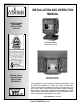
INSTALLATION AND OPERATION MANUAL FREESTANDING AND INSERT PELLET FIRED STOVES Freestanding Model Advantage II-T C FS RETAIN THESE INSTRUCTIONS FOR FUTURE REFERENCE Freestanding Model Advantage II-T C INS These appliances must be properly installed and operated in order to prevent the possibility of a house fire. Please read this entire owner's manual before installing and using your pellet stove. Failure to follow these instructions could result in property damage, bodily injury or even death.
IMPORTANT WARNINGS CAUTION: Read this manual thoroughly before starting installation. For your safety, follow the installation, operation and maintenance instructions exactly without deviation. Failure to follow these instructions may result in a possible fire hazard and will void the warranty. If this appliance is not properly installed, a house fire may result. Contact local building or fire officials about requirements and installation inspection in your area. 1.
TABLE OF CONTENTS Important Warnings ................................................ 2 CONGRATULATIONS ON THE PURCHASE OF YOUR NEW PELLET STOVE MANUFACTURED BY LENNOX HEARTH PRODUCTS. Testing / Listing, EPA, Using this Manual................ 3 Planning Your Installation .....................................
PLANNING YOUR INSTALLATION QUESTIONS TO ASK LOCAL BUILDING OFFICIAL A correct installation is critical and imperative for reducing fire hazards and perilous conditions that can arise when wood pellet burning appliances are improperly installed. The installer must follow all of the manufacturers’ instructions. The installation of this appliance must conform to local codes and applicable state and federal requirements. Familiarity with these requirements before installation is essential.
PLANNING YOUR INSTALLATION FLOOR PROTECTION – Advantage II-T C FS (For USA and CanTop View ada) This appliance requires 3/8" (10 6” mm) minimum non153 mm combustible floor protection designed for solid fuel burning appliances having a thermal conductivity 6” 6” of k = .84 BTU in/ft (153mm) (153mm) min. min. or equivalent. If the floor protection is to be stone, tile, brick, etc.
PLANNING YOUR INSTALLATION Clearances to combustibles are determined from testing to applicable standards for allowable heat transfer. The clearances allowed as shown here, do not take into account operation or serviceability requirements. Alcove - Advantage II-T C FS CLEARANCES Advantage II-T C FS - Standard residential or manufactured (mobile) home installation.
PLANNING YOUR INSTALLATION MASONRY AND FACTORY BUILT FIREPLACES The model Advantage II-T C INS is approved for installation into a solid fuel burning fireplace, either a masonry fireplace (built to UBC 37 or ULC S628 standards) or an approved factory-built / zero clearance fireplace (built to UL 127 or ULC S610 standards). (see pages 19 through 20 for additional information on venting).
PLANNING YOUR INSTALLATION MANUFACTURED (MOBILE) HOME INSTALLATION Freestanding Model – Advantage II-T C FS In addition to the standard installation instructions, the following instructions may be required by local, state or federal building codes: • Stove must be permanently bolted to the floor. • An outside air inlet must be provided for combustion and be unrestricted while unit is in use. Use a galvanized or stainless steel pipe for the duct (the outside air inlet on the stove is 1 5/8" diameter).
INSTALLATION REMOVING APPLIANCE FROM PALLET 1. After removing the packaging from the stove, lift the hopper lid, and remove all pre-packaged items that were shipped in the hopper. Next, open the stove door and remove all pre-packaged items. 2. Using a 9/16” socket or open end wrench, remove the bolts which secure stove to pallet. The bolts are located on the underside of the wooden pallet. ASH PAN COVER ASSEMBLY Remove the ash pan cover trim from hopper.
INSTALLATION INSTALLATION CHECK LIST It is strongly recommended that you have an authorized Lennox Hearth Products dealer install your stove. If you install your stove yourself, you should review your installation plan with an authorized Lennox Hearth Products dealer. Improper installation may void your warranty. Prior to lighting your stove: Review the Important Warnings section (page 2). Review Fuel Specifications (page 25).
INSTALLATION INSTALLING SURROUND ASSEMBLY - Advantage II-T C INS (to be done after venting system is installed) The surround kit (purchased separately) comes with a set of metal panels that enclose the fireplace opening when fitted together. Put the surround assembly together according to the following instructions (ref. see illustration below). 1. 2. 3. 4. 5. 6. 7. 8. 9. Remove panels from package. Verify that you have all three panels and a package with “pop” rivets and #8 self-tapping screws.
INSTALLATION Rear View of Advantage II-T C FS THERMOSTAT INSTALLATION: NOTE: Always Disconnect Power Before Performing The Thermostat Installation. A 24 volt wall thermostat and 20 feet of 18-gage thermostat wire is included in your stove’s accessory package. It is recommended that the thermostat and thermostat wire be installed by an authorized Lennox Hearth Products dealer. Back of Stove Installation Steps: 1. Unplug stove power cord from the wall outlet. 2.
INSTALLATION VENTING REQUIREMENTS It is recommended that only an authorized dealer install your pellet stove. The specified installation requirements must be followed to ensure conformity with both the safety listing of the appliance and local building codes. All clearances, installation instructions and precautions specified by the vent manufacturer must be followed. Selecting a Location (Freestanding Models) - Review the appliance clearance requirements before installing the venting system (see page 6).
INSTALLATION VENT TERMINATION Do not terminate vent in an enclosed or semi-enclosed area such as: carports, garage, attic, crawl space, under a deck, porch, narrow walkway, closely fenced area, or any location that can build up a concentration of fumes such as a stairwell, covered breezeway etc. Vent surfaces can get hot enough to cause burns if touched. Adults should supervise children when they are in the area of a hot stove. Non-combustible shielding or guards may be required.
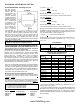
INSTALLATION DETERMINING SIZE OF PIPE TO INSTALL To determine what diameter pipe to use in an installation (3” or 4”), first find the “equivalent pipe length” using the following guidelines, then plot this figure and the altitude on the chart. Fill out the installation chart, and calculate your total equivalent pipe length. After you have the total equivalent pipe length, use the Pipe Selection Chart below to determine if your installation requires 3” or 4” exhaust pipe.
INSTALLATION NOTE: The end of the exhaust pipe must extend a minimum of 12” (305 mm) from the outside of the building. 5. If the installation includes a source of outside combustion air; cut a separate hole through the wall for the fresh air tube. Use a galvanized or stainless steel pipe for the duct. The minimum size for the duct shall be not less than 50% of the cross sectional flue area. Connect outside air pipe to air inlet on stove. This tube must be terminated with a 45 degree elbow or hood.
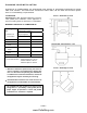
INSTALLATION Standard Horizontal Installation Configurations Advantage II-T C FS* Corner Through the Wall Top View Illustration 3” (75 mm) Minimum clearance between wall and pipe. If you vent to the furthest wall, the vent pipe must maintain a 3” clearance parallel to the other wall.
INSTALLATION Standard Vertical Installation Configurations - Model: Advantage II-T C FS - These freestanding models may be connected to an existing unused flue or by installing type “PL” vent pipe (listed to UL 641 & ULC S609). If a liner is run all the way to the top of the existing chimney, the existing flue should be sealed with a steel plate. Start a vertical run with a Tee at the back of the stove. Other options are illustrated below. Note: See page 13 for Vent Termination Requirements.
INSTALLATION - ADVANTAGE II-T C INS IMPORTANT- Make sure the chimney and firebox are clean and free of soot and ashes before installation begins. Failure to do so may result in the transfer of soot into the room by way of the Room Air Blower.
INSTALLATION INSTALLING ADVANTAGE II-T C INS (CONTINUED) Horizontal Vent Through Masonry Chimney Structure Full Chimney Reline Recommended for All Chimney Installations Seal Chimney top with steel plate and/or pipe support IN CANADA – Installing as a Horizontal Vent is NOT allowed. The fireplace chimney must be fully lined. Listed Rain Cap IMPORTANT NOTES: Approved Liner for Factory Built (ZC) Fireplaces and Masonry Fireplaces is 2100HT (degree F.) liner listed to UL 1777 or ULC S635.
CARE AND OPERATION CONTROL BOARD OPERATION Control Board Start Button – The push button Start Button activates the room air and the exhaust blowers. If the exhaust temperature does not reach operating temperature within 30 minutes, the stove will automatically shut down. The blowers can be restarted by pushing the Start Button again. Auger On/Off Button – The Auger On/Off Button activates the fuel feed (auger motor) only. The light located just above the button will blink when the auger is turning.
CARE AND OPERATION Fuel Delivery Rate The Heat output button manages the fuel delivery rate by controlling the amount of time the auger motor will run (Settings: 1 = Low, 2 Medium Low, 3 Medium, 4 Medium High, 5 High). PRE-LIGHTING INSTRUCTIONS During an initial start-up, or in the case where the hopper has run out of fuel, it will be necessary to prime the auger feed system. To prime the auger feed tube: 1. Fill the hopper with recommended pellet fuel and plug the stove into the wall outlet. 2.
CARE AND OPERATION Continued from last page… 1. Place a recommended fire starter (see your dealer for appropriate fire starter in your area) in the UltraGrateTM and put a handful of pellets on top of the starter. DO NOT USE FLAMMABLE LIQUIDS TO START YOUR STOVE. 2. Light the fire starter in the UltraGrateTM with a match and close the door. Press the heat output selector button to position 3. 3. After approximately 10 seconds, press the START button.
CARE AND OPERATION Continued from last page… Any adjustments for combustion air should be made at the damper by varying the spacing between the side of the stove and the inside of the damper set collar. The factory setting on the damper, as noted above, should correspond with the model you have. If the fire goes out on the #1 setting, you will want to decrease the combustion airflow. Loosen the set collar and push the damper in by 1/4” intervals. Tighten the collar at its new position (2 1/2” – 2 3/4”).
CARE AND OPERATION FUEL Clinkering - Silica (or sand) in the fuel, along with other impurities, can cause clinkering. A clinker is a hard mass of silica formed in the burning process. Clinkering is a function of the fuel, (not the stove), but adversely affects the performance of the stove by blocking off the air passages in the UltraGrateTM. Even a P.F.I. approved pellet fuel may tend to clinker.
ROUTINE MAINTENANCE Inspect your stove or insert at minimum frequency stated until you establish a minimum frequency required for your installation (frequency will vary depending upon fuel BTU value / ash content, usage, and misc. installation variables). ROUTINE CLEANING Stove will need to be shut off and cooled enough to handle before routine cleaning is performed. All ash removal and cleaning should be done while stove is cold. Always disconnect power before doing any routine cleaning.
ROUTINE MAINTENANCE ASH TRAP AND BAFFLES Access to the ash trap baffles (behind the two side firebricks) is obtained by loosening the screws that hold the Brick Retention Plates in place and lifting the clips away from the stove. After the clips have been removed, remove the side bricks first, then the center firebrick. Thoroughly clean out the areas where ash has collected behind the firebrick. The amount of time between cleanings will be directly related to the ash content of the pellet fuel being burned.
ROUTINE MAINTENANCE EXHAUST PASSAGES AND VENT PIPE (All Models) Inspect frequently and clean when necessary. Fly ash will accumulate at all bends in the exhaust system. Note: Large amounts of fly ash build-up will create a lack of combustion air. Removing the clean out tee cap on vertical installations will allow an inspection of the ash buildup in the clean out tee and will help you to decide how frequently more extensive cleaning must be performed.
ROUTINE MAINTENANCE WINDOW WASH Periodically remove four screws which secure the window wash bracket to the door frame, using a 1/4” socket. Lift out the widow wash bracket, and set aside. Using a small brush, sweep out all debris buildup from behind the window wash bracket. After all debris has been removed re-attach the window wash bracket. OPENING SIDE PANELS Advantage II-T C FS – For right hand side panel open the glass door, locate the 2 screws at front edge and remove using a 5/16” nut driver.
ROUTINE MAINTENANCE SMALL AREA PAINT TOUCH-UP The stove body is painted with a quality hightemperature stove paint. Use only Stove Paint, Part # 70K99. Do not touch-up your stove with any other paint. Using one small piece of 320 grit sand paper and lightly sand the blemish so that the edges are “feathered” or smooth to the touch between the painted and bare surfaces. Do not let the sand paper gum up with paint, as this will cause scratches on the metal surface.
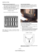
SPECIFICATIONS - Advantage II-T C FS SIDE VIEW ILLUSTRATION Flue Size 3” Standard Width, Overall 24 3/4” Depth, Overall Depth, Overall w / 3” tee 25” (26" to flue outlet) 30 7/8” Height 31 3/8” Floor to Rear Flue Center 17 1/2” Facing Back of Unit, outside edge on right to center of rear flue outlet 5 15/16” Floor to Rear Outside Air Inlet 11" Facing Back of Unit outside edge on right to center of air inlet 13 1/2” Floor Protection Requirements + 30 7/8” 24 3/4” 6" Front & Sides & up to
SPECIFICATIONS - Advantage II-T C INS Flue Size 3” Standard Width, Overall front (w/o surround) Width, Overall back (w/o surround) 25” 24 1/4” Depth, Overall (w/o surround) 24 3/4” Height, rear (w/o surround) Height, front (w/o surround) 19 3/4” 22 3/4” Floor to Rear Flue Center 8 1/2” Fireplace Face to Rear Flue Outlet Center (3” tee) 17 3/8” Dimensions into Fireplace Minimum Height Minimum Width @ Front (extends back 1 ½”) Minimum Width @ Back Minimum Depth 32” 24 5/8” 17 3/4” Facing Back of
COMPONENT DEFINITIONS detect reversed flow. If negative pressure in the dwelling (i.e. An extremely tight house which may not supply adequate combustion and ventilation air) causes the exhaust to pull back from the combustion air inlet, the heat from the exhaust will result in heat activation of this disc. AIR WASH To inhibit buildup of soot on the door glass, air is delivered to the glass through an air wash system located in the doorframe surrounding the glass.
WIRING DIAGRAM PAGE 34 www.PelletKing.
TROUBLESHOOTING Qualified Technicians Only Unplug Appliance Before Performing Any Troubleshooting or Maintenance PROBLEM 1. Fire burns with a lazy orange flame. Pellets build up in the UltraGrateTM and the window gets sooted up. CAUSE(S) There is insufficient combustion air. SOLUTIONS Remove any clinkers or ash from the bottom of the UltraGrateTM that might be obstructing the primary air holes. Change to a better grade of fuel if necessary.
TROUBLESHOOTING Qualified Technicians Only Unplug Appliance Before Performing Any Troubleshooting or Maintenance PROBLEM 4. Pellets will not feed. CAUSE(S) The hopper is empty. SOLUTIONS Refill hopper. The auger motor or circuit board, air inlet high limit switch or pressure switch may be defective. The pressure switch tap or hose may be blocked. Check to be sure that there is no blockage in the pressure tap or hose.
TROUBLESHOOTING Qualified Technicians Only Unplug Appliance Before Performing Any Troubleshooting or Maintenance PROBLEM 9. There is soot or fly ash in the house. 10. Blinking red lights on control board LED's. CAUSE(S) The window is being cleaned or ash pan removed when the stove is operating. SOLUTIONS Turn down the Room Air Blower or turn off stove before cleaning to prevent dispersion of ash and soot into the room.
REPLACEMENT PARTS LIST Door Parts 12140510 Bracket, Door Hinge 12151505 Bracket Kit, Window Wash 12150500 Door Assembly, Complete, Advantage II-T C- Black (3 pc) 61057100 Gasket Kit, Door Rope (WP2/WP4; 1/2" round; 7 ft.; firm) 61057201 Gasket Kit, Glass (WP2; 10 feet; 5/8", black with adhesive) 12146400 Glass, Center (13" x 9") (with gasket) 12146401 Glass, Side (4.3" x 9") (with gasket) 12054200 Handle Kit, Oak Door (WP2/WP4) – 2 per pkg. 12150507 Hinge Pin, Door (WP2/WP3; 5/16” x 1-1/2”) – 2 per pkg.
REPLACEMENT PARTS LIST Freestanding Only Parts 12251405 Lid with Hinge, Hopper (Freestanding) - Black 12254000 Panel, EZ Open, Left Side - Black 12256000 Panel, EZ Open, Right Side – Black 12255001 Panel, Top, F|S, Black 12252900 Trim Kit, Brass (for Side Panel, WP2 – Freestanding) – 2 per pkg.
REPLACEMENT PART DIAGRAMS Wall Thermostat Kit Firebrick Kit 3 Piece Set UltraGrateTM Kit Door Assembly Power Cord Kit Glass (Order each pc. separately. Gasket Included) PAGE 40 www.PelletKing.
REPLACEMENT PART DIAGRAMS Pressure Switch Kit Auger Motor (hose not included) Room Air Blower Auger Set Collar Exhaust Blower Auger End Plate Gasket Control Board Damper Rod PAGE 41 www.PelletKing.
OPTIONAL ACCESSORIES LIST AND DIAGRAMS Catalog # H0423 70K99 H0424 H0425 H0426 H0427 H0428 H0429 H0452 H0430 Model TKAIIT-G TSPK-B SKSAIIT SKMAIIT SKLAIIT STKSAIIT-G STKMAIIT-G STKLAIIT-G HEK-AIIT DLS-AIIT Description Trivet, Gold Touch-up Spray Paint Kit, Flat Metallic Black Surround Kit, Small, 28 1/2” x 40 3/4”, Black Surround Kit, Medium, 32” x 44”, Black Surround Kit, Large, 36 x 48”, Black Surround Trim Kit, Small, 28 1/2” x 40 3/4”, Gold Surround Trim Kit, Medium, 32” x 44”, Gold Surround Trim Kit,
ADVANTAGE II-T C PELLET STOVE SAFETY LABEL Note that your stove’s serial number is printed on the safety label, which is located near the inside of the hopper. Your stove’s serial number is preceded by a “WH-”(Example WH-0000000). PAGE 43 www.PelletKing.
ADVANTAGE II-T C: EPA LABEL & COLORADO COMPLIANCE LABEL PAGE 44 www.PelletKing.
SIMPLE OPERATING INSTRUCTIONS LABEL PAGE 45 www.PelletKing.
INSTALLATION TIPS PAGE 46 www.PelletKing.
OWNERSHIP RECORDS Dealer’s Name: Dealer’s Address: City: State: Zip Code: Serial Number: Date of Purchase: Date Installed: Notes: SERVICE AND MAINTENANCE LOG Service Service Service Date Technician Description PAGE 47 www.PelletKing.
1110 West Taft Avenue Orange, CA 92865 www.PelletKing.