
Datasheet


1
2
8 www.lemo.com
®
®
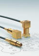
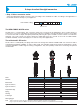
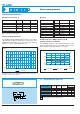
Metal housing models
~18
~26
S 4.5
ø 6.4
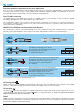
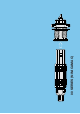
FFA Straight plug with cable collet
M1
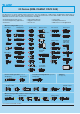
Cable assembly, solder contact (page 39)
Part number
FFA.00.250.NTAC15
FFA.00.250.NTAC17
FFA.00.250.NTAC22
FFA.00.250.NTAC27
FFA.00.250.NTAC31
Cable Cond. Dielectric Ø Sheath Ø
group Ø max. max. min. max.
9 0.55 1.45 1.1 1.4
– 0.55 1.45 1.3 1.7
1 0.55 1.95 1.8 2.2
2-3-4 0.55 1.95 2.3 2.7
8 0.55 1.95 2.8 3.0
Characteristics
Value Standard Test
Contact retention force
Cable pull off force
1)
Connector pull off force
Endurance
Operating temperature
> 18 N IEC 60512-8 15a
> 100 N IEC 60512-9 17c
> 90 N IEC 60512-8 15f
> 5000
IEC 60512-5 9a
cycles
- 55°C + 260°C
Characteristics
Value Standard Test
Impedance
Operating voltage (50 Hz)
Test voltage (50 Hz)
Rated current
Contact resistance
Shell electrical continuity
Insulating resistance
VSWR
Shielding efficiency
50 Ω –
0.7 kV rms –
2.1 kV rms IEC 60512-2 4a
4 A IEC 60512-3 5a
< 6 mΩ IEC 60512-2 2a
< 3.5 mΩ IEC 60512-2 2f
> 10
12
Ω IEC 60512-2 3a
see chart N°1 below
see chart N°2 below
Mechanical and climatical Electrical
Technical Characteristics
Note:
1)
depending on cable design
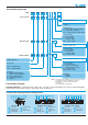
Voltage Standing Wave Ratio
The VSWR (Voltage Standing Wave Ratio) is the value
representing the power reflected in a connection. The
VSWR varies with frequency, in most cases, the working
frequency range is where VSWR is ≤ 1.25.
75
Ω
1500 500 1000 f
1.1
1.0
VSWR
FFS + PCS
1.2
1.3
50Ω
Note: value for connectors with PTFE insulator. VSWR measured
50 Ω with a RG-174 A/U cable and 75 Ω with a RG-179 B/U cable.
Measured according to IEC-60169-1-1.
-40
-30
-20
-10
0.01 0.1 1 10 100 1000 f
(MHz)
120
100
80
60
(dB)
(dB
Ω
)
FFA + PCA FFS + PCS FFV + PCS
Shielding efficiency (EMC properties) in dB
(transfer impedance in dBohm)
The shielding efficiency is the ratio between the electro-
magnetic field inside the connector and a power source
at the outside of the connector (or vice versa).
Note: measured according to IEC-60169-1-3 standard.