00 NIM-CAMAC & 01 COAXIAL CONNECTORS
® ® LEMO coaxial 00 and 01 Series ( 50 Ω ) Fundamental research in particle physics as practised within CERN and other nuclear research establishments requires more and more complex equipment of high performance in order to achieve the objectives. The needs of such research contribute to the development of leading products for the whole of industry. For many years LEMO has participated in this evolution.
® ® Precision modular connectors to suit your application Since its creation in Switzerland in 1946 the LEMO Group has been recognized as a global leader of circular Push-Pull connectors and connector solutions. Today LEMO and its affiliated companies, REDEL and COELVER, are active in more than 80 countries with the help of over 40 subsidiaries and distributors.
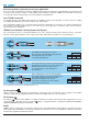
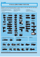
® ® 2 steps to select the right connector ● Step 1: Select connector series Select the appropriate LEMO connector series according to the standard, the cable, according to the application or the mated connector already on your equipment. . 250 . . Part number coding 00 or 01 series The NIM-CAMAC 00 .250 series The 00 series is coaxial (50 Ω ). This connectors family was conceived for all applications where a high density of connectors is necessary, especially for patch panels.
® ® ● Step 2 : Complete the part number Complete the part numbering by choosing the model depending on your cable and the application. . 250 . .
00 SERIES (NIM-CAMAC) ® www.lemo.
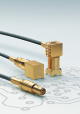
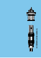
® ® 00 Series (NIM-CAMAC CD/N 549) The 00 series is a range of 50 Ω coaxial connectors. They are suitable for a wide variety of applications particularly in measurement, control system and nuclear physics, having formed the basis for the NIM-CAMAC CD/N 549 standard.
® ® Part Numbering System Plug FFA . 00 . 250 . N T A C 29 Free socket PCA . 00 . 250 . N T L C 29 Variant: (page 30) Cable ø Collet type: C = with cable collet clamping E = with cable crimping K, D = with oversize cable collet Fixed socket ERA . 00 . 250 . N T Contact type : A = male solder C = male crimp L = female solder M = female crimp L Variant: (page 30) Fixed coupler RAD . 00 . 250 .
® ® Metal housing models Technical Characteristics Mechanical and climatical Characteristics Electrical Value Standard Test Characteristics Impedance Operating voltage (50 Hz) Test voltage (50 Hz) Rated current Contact resistance Shell electrical continuity Insulating resistance VSWR Shielding efficiency Contact retention force Cable pull off force 1) Connector pull off force > 18 N > 100 N > 90 N IEC 60512-8 IEC 60512-9 IEC 60512-8 15a 17c 15f Endurance > 5000 cycles IEC 60512-5 9a - 55°C +
® ® FFA Straight plug with oversize cable collet Part number FFA.00.250.NTAK37 FFA.00.250.NTAK42 ~ 36.5 ø8 ø 6.4 ~ 28.5 S 6.5 M1 Cable group Cond. Ø max Dielectric Ø maxi 8 – 0.55 0.55 1.95 1.95 Sheath Ø mini maxi 3.0 3.3 3.6 4.1 Cable assembly, solder contact (page 39) S7 FFA Straight plug with cable collet and nut for fitting a bend relief ~33.5 ø 6.4 ~25.5 Part number Cable group Cond. Ø max Dielectric Ø maxi FFA.00.250.NTAC15Z FFA.00.250.NTAC17Z FFA.00.250.NTAC22Z FFA.00.250.
® ® FFY Straight plug, large shell with cable collet Part number ~33 ø 8.9 ø 8.6 ~25 FFY.00.250.NTAC40 FFY.00.250.NTAC47 FFY.00.250.NTAC52 M2 S7 Cable group Cond. Ø max Dielectric Ø maxi 5 – 6-7 1.05 1.05 1.05 3.05 3.05 3.05 Sheath Ø mini maxi 3.2 3.9 4.6 3.8 4.5 5.0 Cable assembly, solder contact (page 39) S8 FFE ~33.5 ø 7.4 ~25.5 Straight plug with front sealing ring, cable collet and nut for fitting a bend relief (IP 54 protection index when mated) Part number Cable group Cond.
® ® FFV Straight plug for cable crimping with improved screen efficiency 1) Part number FFV.00.250.NTAE24 FFV.00.250.NTAE31 FFV.00.250.NTAE52 M5 L FFV.00.250.NTCE24 FFV.00.250.NTCE30 FFV.00.250.NTCE31 FFV.00.250.NTCE35 FFV.00.250.NTCE44 FFV.00.250.NTCE52 FFV.00.250.NTCE56 ø 6.4 S 5.5 S 5.5 M4 Dim M 31 31 34 Cable Cond. group Ø maxi 23 23 26 1 3-4 6 Dielec. Ø maxi Sheath Ø maxi 0.95 1.65 3.05 2.35 3.0 5.2 0.4 0.55 0.
® ® FLV Elbow plug (90°) for cable crimping with improved screen efficiency * 17.5 Part number ø9 9.5 H FLV.00.250.NTAE31 FLV.00.250.NTAE35 FLV.00.250.NTAE52 FLV.00.250.NTAE56 M7 H Cable (mm) group 15 15 18 18 3-4 8 6 7 Cond. Ø maxi Dielectric Ø maxi Sheath Ø maxi 0.55 0.55 0.97 0.97 1.65 1.65 3.05 3.05 3.0 3.35 5.2 5.45 Cable assembly, solder contact (page 42) * Screen efficiency >100dB at 1 GHz, see page 8. FAA Straight plug, non-latching, nut fixing 15.
® ® ERA Fixed socket, nut fixing 15 1 S9 ø8 ø 10.2 M7x0.5 Part number 5.5 maxi ERA.00.250.NTL S 6.3 P5 Weight (g) 2.5 Panel cut-out (page 38) ERN Fixed socket, nut fixing, with earthing tags 15 S9 1 ø8 ø 10.2 M7x0.5 Part number 5.5 maxi ERN.00.250.NTL S 6.3 P5 Weight (g) 2.5 Panel cut-out (page 38) ERC Fixed socket, with thread, with slots in flange 1 1.6 Part number ø8 ø 10.2 M7x0.5 15 S9 ERC.00.250.NTL Weight (g) 2.
® ® ERM Fixed socket, nut fixing, with microswitch 20 1 S9 ø8 ø 10.2 M7x0.5 Part number ERM.00.250.NTL Weight (g) 3.0 A 5.5 maxi S 6.3 P5 Panel cut-out (page 38) Technical characteristics on request B ERX Fixed socket, with thread, with slots in flange, with earthing tags 15 1.6 1 ø8 Part number ERX.00.250.NTL Weight (g) 2.0 P3 Panel cut-out (page 38) ECP Fixed socket with two nuts 15 2 ø9 ø9 M7x0.5 Part number ECP.00.250.NTL Weight (g) 3.
® ® EPA-EPB Straight socket for printed circuit 7 ø 0.7 (5X) 17 5.08 L ø 6.8 Part number EPA.00.250.NTN EPB.00.250.NTN L (mm) Weight (g) 14 12 3.4 3.3 P10 PCB drilling pattern (page 38) EPC Straight socket for printed circuit with clearance under the body 7 ø 0.7 (5x) 17 5.08 14 ø 6.8 Part number EPC.00.250.NTN Weight (g) 3.3 P10 PCB drilling pattern (page 38) EPE Fixed socket with two nuts, for printed circuit 17 14 2.5 ø 10.2 ø 0.7 (5x) S9 7 3.5 maxi ø 10 M7x0.5 Part number EPE.
® ® EPK Elbow socket (90°) for printed circuit with clearance under the body 7 ø 6.8 5.08 Part number 17.5 4.2 10 7 EPK.00.250.NTN Weight (g) P10 PCB drilling pattern (page 38) ø 0.7 (5x) EPS Elbow socket (90°) with two nuts, for printed circuit 7 M7x0.5 ø 10.2 2.5 5.08 Part number Weight (g) S9 EPS.00.250.NTN 5.4 17.5 10 7 ø 10 P1 ø 0.
® ® EPN Straight socket for press mounting in pair on printed circuit Part number EPN.00.250.NTN 0.8 Weight (g) 3.6 5.08 ø 1.5 P9 PCB drilling pattern (page 38) 14 7 10.7 8.7 maxi 8.3 mini ø6 3.5 1.7 maxi 1.3 mini ø 0.9 (2x) 2 PCA Free socket with cable collet ø 6.5 ~25 Part number Cable group Cond. Ø max Dielectric Ø maxi PCA.00.250.NTLC15 PCA.00.250.NTLC22 PCA.00.250.NTLC27 PCA.00.250.NTLC31 9 1 2-3-4 8 0.55 0.55 0.55 0.55 1.45 1.95 1.95 1.95 M1 Sheath Ø mini maxi 1.1 1.7 2.
® ® PSS Fixed socket, nut fixing, for cable crimping Part number Dim L Cable group PSS.00.250.NTME24 PSS.00.250.NTME30 PSS.00.250.NTME31 PSS.00.250.NTME35 PSS.00.250.NTME52 30 30 30 30 33 1 2 3-4 8 6 L S9 S 5.5 M7x0.5 5.5 maxi ø 10.2 ø8 1 Cond. Ø Dielec. Sheath mini maxi Ø maxi Ø maxi 0.28 0.4 0.28 0.4 0.46 0.55 0.46 0.55 0.90 0.97 0.95 1.65 1.65 1.65 3.05 2.35 3.0 3.0 3.35 5.2 S 6.
® ® FRT Straight plug with resistor 29 21 ø 6.4 Part number FRT.00.250.NTA00 FRT.00.250.NTA50 FRT.00.250.NTA100 Resistor Weight (g) shorted 50 Ω 0.6W 100 Ω 0.4W 4.4 4.4 4.4 Note S 5.5 Note: Standard, first choice alternative Non standard, on request only FLR Elbow plug (90°) with resistor 17.5 ø9 9.5 18.8 Part number FLR.00.250.NTA50 Resistor Weight (g) 50 Ω 0.6 W 5.6 RAD Fixed coupler, nut fixing 22 S9 1 M7x0.5 ø 10.2 ø8 Part number RAD.00.250.NTM P5 5.5 maxi S 6.3 Weight (g) 3.
® ® FTA T-plug with two sockets in line Part number 30 FTA.00.250.NTF 7.8 17.5 9.5 ø9 Weight (g) FTL T-plug with two sockets (90°) Part number 28 ø9 FTL.00.250.NTF Weight (g) 7.1 18.5 20 FTY Straight plug with two parallel sockets Part number 29.5 7 21.5 FTY.00.250.NTF Weight (g) 12.5 20 ø 16 7 Note: Test voltage: 1.1kV (rms) / IEC 60512-2 test 4a. www.lemo.
® ® Plastic housing models This plastic housing provides the ideal solution when the isolation of the connector is critical (non metallic). The FFA and ERN models in PEEK allow weight saving and can provide ease of use in applications such as medical electronic instrumentation.
® ® Watertight or vacuumtight models A range of sealed sockets and couplers allows the device on which they are fitted to reach a protection index of IP68 as per IEC 60529 (unmated). They are fully compatible with plugs of the same series and are widely used for portable radios, military, laboratory equipment, aviation, etc. These models are identified by a letter «P» at the end of the reference for watertight model and by a «PV» for vacuumtight models.
® ® EWF Fixed socket, nut fixing, watertight or vacuumtight (back panel mounting) 17 3 S9 ø 10.2 ø 11 M7x0.5 Part number EWF.00.250.NTLP EWF.00.250.NTLPV Weight (g) 4.2 4.2 9.5 maxi S9 P1 Panel cut-out (page 38) EWV Fixed socket, screw fixing, watertight or vacuumtight 17 Part number ø 11 EWV.00.250.NTLP EWV.00.250.NTLPV ø 7.9 M7x0.5 ø 1.5 2.6 P2 Weight (g) 3.7 3.7 Panel cut-out (page 38) SWH Fixed coupler, nut fixing, vacuumtight 24.5 1.5 S9 M7x0.5 ø 11 ø 10.2 Part number SWH.
® ® Metal housing models with mechanical keying The straight plug and receptacle models FSG,XBG,XRG,XSG,ESG,EXG and PSG are available with a key to avoid cross mating of similar connectors. These models are not included in the NIM-CAMAC standard. The standard "G" key consists of one mechanical alignment key. Front view of the standard "G" key FSG Straight plug with key (G), with cable crimping Part number FSG.00.250.NTAE24 FSG.00.250.NTAE31 FSG.00.250.NTAE52 M5 L L 31 31 34 ø 6.4 Part number FSG.00.
® ® XSG Elbow socket (90°) with slotted with key (G), and hex nuts for printed circuit S9 7 2.5 ø 10.3 M7x0.5 5.08 Part number XSG.00.250.NTN 17.5 7 ø 10 P1 Weight (g) 5.4 Panel cut-out (page 38) 3 P12 PCB drilling pattern (page 38) ø 0.7 (5 x) 4 maxi ESG Fixed socket with two round nuts, threaded shell, with key (G) (back panel mounting) 15 Part number ø9 ø9 M7x0.5 2 ESG.00.250.NLL Weight (g) 3.
® ® Threaded-coupling models The straight plug and receptacle models FVS, EPE and EPS are available with threaded coupling. On sockets, 3.2 mm minimum length of free threading must be available to ensure screw mating. These models are not included in the NIM-CAMAC standard. FVS Straight plug for cable crimping Part number FVS.00.250.NTAE24 FVS.00.250.NTAE31 FVS.00.250.NTAE52 M5 M FVS.00.250.NTCE24 FVS.00.250.NTCE25 FVS.00.250.NTCE30 FVS.00.250.NTCE31 FVS.00.250.NTCE35 FVS.00.250.NTCE44 FVS.00.250.
® ® Adaptors ABF Adaptor from LEMO plug to BNC socket 36 Part number 28 8.3 ø 11.5 ABF.00.250.NTA Weight (g) Part number 35.5 APF.00.250.DTAB APF.00.250.DTAR ø 6.4 ø 8.3 ø 4.6 APF Adaptor from LEMO plug to CINCH socket Colour of the ring Weight (g) white red 7 7 43.5 ABA Adaptor from LEMO socket to BNC plug ø 14.5 28.5 Part number ABA.00.250.NTL Weight (g) 18.7 ABC Adaptor from LEMO socket to BNC socket ø 14.5 29.5 Part number S 16 S 17 Part number ABD.00.250.NTM P7 S 11.
® ABB Adaptor from LEMO fixed socket to BNC socket 3/8-32 UNEF - 2A ® 25 Part number ø 14 S 11 ABB.00.250.NTM P6 Weight (g) 9.4 Panel cut-out (page 38) 9.5 maxi S 8.7 ACA Adaptor from LEMO socket to C plug 31 ø 19.5 Part number ACA.00.250.NTL Weight (g) 32 Note: Non standard, on request only AGH Adaptor from LEMO socket to UHF plug ø 18.5 26 Part number AGH.00.250.NTL Weight (g) 13.8 ANA Adaptor from LEMO socket to N plug 33.5 ø 20.5 Part number ANA.00.250.
5/8 - 24 UNEF - 2A ® 46 ® ANC Adaptor from LEMO socket to N fixed socket S 19 ø 21.8 Part number ANC.00.250.NTM P8 S 13.5 Weight (g) 63.5 Panel cut-out (page 38) 17 maxi Note: Non standard, on request only ASA Adaptor from LEMO socket to SMA plug 30 ø9 Part number ASA.00.250.NTL Weight (g) 4.9 S8 1 / 4 - 36 UNS - 2A ASB Adaptor from LEMO socket to SMA socket 30.8 ø9 Part number ASB.00.250.NTM Weight (g) 4.6 S8 1 / 4 - 36 UNS - 2A ASF Adaptor from LEMO plug to SMA socket 31.8 23.
® ® Variant Bend relief for models with collet (letter Z in the variant position) Need to be ordered Reference Need to be ordered separately (see page 33) C15Z C17Z C22Z C27Z C31Z C52Z K37Z K42Z D42Z D52Z GMA.00.0●●.D● GMA.00.0●●.D● – GMD or GMB.00.0●●.D● GMD or GMB.00.0●●.D● GMA.0B.0●●.D● GMA.0B.0●●.D● GMA.0B.0●●.D● GMA.0B.0●●.D● GMA.0B.0●●.
® ® Assembled cables MFB models MSB models Delay lines Part number MFB.00.250.RTE005 MFB.00.250.RTE010 MFB.00.250.RTE020 MFB.00.250.RTE030 MFB.00.250.RTE040 MFB.00.250.RTE050 MFB.00.250.RTE060 MFB.00.250.RTE080 MFB.00.250.RTE100 MFB.00.250.RTE160 MFB.00.250.RTE200 MFB.00.250.RTE320 MFB.00.250.RTE640 Assembled Cables Delay (ns) 0.5 1.0 2.0 3.0 4.0 5.0 6.0 8.0 10.0 16.0 20.0 32.0 64.0 Part number MSB.00.250.RTE005 MSB.00.250.RTE010 MSB.00.250.RTE020 MSB.00.250.RTE030 MSB.00.250.RTE040 MSB.00.250.
® ® BRA Blanking cap for fixed socket and free straight socket 9 3.5 9.8 ø 7.5 Part number ø 3.5 60 BRA.00.200.PCSG Weight (g) 0.6 Note: upon request this cap can be supplied in black and the last letter “G” of the part number should be replaced with “N”.
® ® GM• Bend relief A Dim. L ø Cable max min Nut for fitting the bend relief part nb GMA.00.012.D • GMA.00.018.D• GMB.00.025.D• GMB.00.028.D• GMB.00.032.D• GMD.00.025.D• GMD.00.028.D• GMD.00.032.D• 1.2 1.8 2.5 2.8 3.2 2.5 2.8 3.2 22 22 22 22 22 22 22 22 1.4 2.1 2.8 3.1 3.5 2.8 3.1 3.5 1.1 1.8 2.5 2.8 3.2 2.5 2.8 3.2 FFM.00.130.LN FFM.00.130.LN FFM.00.130.LN FFM.00.130.LN FFM.00.130.LN FFM.00.130.LN FFM.00.130.LN FFM.00.130.LN GMA.0B.025.D • GMA.0B.030.D• GMA.0B.035.D• GMA.0B.040.D• GMA.0B.045.
® ® GBB Tapered washer ø9 2 ø 7.1 Weight (g) Part number GBB.00.250.LN 0.2 Note: to order this accessory separately, use the above part number. ● Material: Brass (UNS C 38500) nickel-plated (3 µm) GBA Locking washer ø9.5 1 ø7.1 Weight (g) Part number GBA.00.250.FN 0.2 Note: sockets and plugs are always supplied with a locking washer. To order this accessory separately, use the above part number. GEA Hexagonal nut 9 2 M7 x 0.5 Weight (g) Part number ø 10.2 GEA.00.240.LN 0.
® ® GEB Slotted nut øA L e A Dimensions (mm) B e GEB.00.242.LN 8.5 10 M7 x 0.5 Standard for models L øB Part number 2.5 ELF, XBG, XRG, XSG, EXG Note: to order this accessory separately, use the above part numbers. ● Material: Brass (UNS C 38500) nicked-plated (3 µm) GCA Earthing Washer ø 9.5 0.4 ø 7.1 18.2 Part number GCA.00.255.LT Weight (g) 0.
® ® DCB Spanner for slotted nut 60 Part number of the nut 19 Part number DCB.91.455.0LN GEB.00.242.LN ø 11 ● Material: Steel, nicked plated DCB Spanner for round nut 50 Part number of the nut 40 Part number DCB.91.119.0TN GEB.00.240.LN ø 11 ● Material: Blackened steel DCN Spanner for assembling plug with 3 latches 12 Part number 42 ø9 DCN.91.905.0TK ● Material: Blackened steel DCP Flat spanner for collet nut L Dimensions M N S1 M Part number DCP.99.045.TC DCP.99.050.TC DCP.99.
® ® DPE Crimping tool with die Part number DPE.99.000.00 DPE.99.123.1K DPE.99.123.8K DPE.99.124.3K DPE.99.125.2K DPE.99.176.2K Cable group Crimp collet ref. Crimping tool with no die 1 E24 2-3-4 E30, E31 8 E35 5 E44 6-7 E52, E56 DPN Dies Part number A A DPN.99.123.1K DPN.99.123.8K DPN.99.124.3K DPN.99.125.2K DPN.99.176.2K 1 2-3-4 8 5 6-7 Die dimension For contacts For shield A B L A B 1.29 1.29 1.29 1.29 1.71 0.91 0.91 0.91 0.91 1.21 2.0 2.0 2.0 2.0 2.5 3.10 3.80 4.36 5.20 6.20 2.70 3.30 3.
® ® Panel cut-outs Panel cut-out P1 P2 P3 P4 P5 Cut-out P1 B + 0.1 0 L mini e P6 P7 øA P2 P3 P4 + 0.1 0 P8 P5 B + 0.1 0 L mini øA P6 P7 P8 Model ECP-EPE-EPR-EPS-ERC EWF-EXG-FAB-HGP HGW-SWH-VPS-XBG XSG-XRG EWV ERC-ERX ERT EHP-ELF-ERA-ERE-ERM ERN-FAA-FAN-PES-PFS PLK-PSA-PSG-PSS 1) ABB ABD ANC Dimensions B L A e 7.1 – 14.5 – – – 6.92 + 0.02 0 – – – 12.0 9.0 – M7x0.5 M7x0.5 – 7.1 6.4 14.5 – 9.7 12.9 16.1 9.0 11.7 13.7 15.0 20.5 24.
® ® Cable assembly Terminating of plugs and straight sockets with cable collet 5 M1 M2 4 M3 3 1 Straight plug 2 5 Free socket 3 4 5 1 Fixed socket nut fixing 1. Cable preparation First place the bend relief (if to be used) on the cable. Strip the cable according to dimensions below. L ± 0.2 S ± 0.2 Cable group T M1 S L T M2 S L T M3 S L 1-2-3-4-8 6-7 4 – 4.5 – 9 – – 7.5 – 8.5 – 13 5 – 5 – 8 – T ± 0.2 2. Cable termination 2.
® ® Terminating of plugs and straight sockets with cable crimping (crimp contact) 4 M4 2 3 Straight plug 1 4 Free socket 3 2 4 Fixed socket nut fixing 1. Cable preparation First place the bend relief (if to be used) on the cable. Strip the cable according to dimensions below. L ± 0.2 S ± 0.2 Cable group T M4 S L 1-2-3-4-8 6-7 7 7 15 15 19.5 21.5 T ± 0.2 2. Cable termination 2.1 Place crimp ferrule ➀ on the cable. Widen the shield braid.
® ® Terminating of plugs and straight sockets with cable crimping (solder contact) 4 M5 2 3 Straight plug 1 4 Free socket 3 2 4 Fixed socket nut fixing 1. Cable preparation First place the bend relief (if to be used) on the cable. Strip the cable according to dimensions below. L ± 0.2 S ± 0.2 Cable group T M5 S L 1-2-3-4-8 6-7 5 5 12 12 17 19 T ± 0.2 2. Cable terminating 2.1 Place the crimp ferrule ➀ on the cable. Widen the shield braid.
® ® Terminating of elbow plugs (90°) with cable collet (solder contact) 3 M6 and cable crimp (solder contact) M7 5 4 2 3 4 2 1 1 1. Cable preparation 1. First place the bend relief (if to be used) on the cable. Strip the cable according to dimensions below. L ± 0.2 S ± 0.2 2. Solder 42 Cable group T M6 S L 1-2-3-4-8 1 3.5 6.5 First place the bend relief (if to be used) on the cable. Strip the cable according to dimensions below. L ± 0.2 S ± 0.2 T ± 0.2 T ± 0.
01 SERIES www.lemo.
® ® 01 Series The plugs and sockets of the 01 series are amongst the smallest available 50 Ω coax connectors with a self-latching intermating capability. In spite of their small size and light weight, their technical characteristics remain excellent. Available in a wide range of housing configurations, they are especially useful when connecting onto printed circuit boards.
® ® Part Numbering System Plug FFS . 01 . 250 . D L A E 31 Free socket PCS . 01 . 250 . D L L E 31 Cable ø Collet type: E = with cable crimping Contact type: A = male solder L = female solder Fixed plug FPA . 01 . 250 . D L D Fixed socket ERA . 01 . 250 . D L L Contact type: L = female solder N = female print D = male print Fixed coupler RAD . 01 . 250 .
® ® Metal housing models Technical Characteristics Mechanical and climatical Characteristics Voltage Standing Wave Ratio Value Standard Test Contact retention force Cable pull off force 1) Connector pull off force > 60 N > 100 N > 110 N IEC 69512-8 IEC 69512-9 IEC 69512-8 15a 17c 15f Endurance > 1000 cycles IEC 69512-5 9a Operating temperature Note: - 55°C + 230°C The VSWR (Voltage Standing Wave Ratio) is the value representing the power reflected in a connection.
® ® FLS Elbow plug (90°) for cable crimping 12.1 ø 7.5 6.6 Part number 12 FLS.01.250.•LAE24 FLS.01.250.•LAE31 M2 Cable group Cond. Ø max Dielectric Ø max Sheath Ø max 1 2-3-4 0.5 0.5 0.95 1.65 2.35 3.0 Cable assembly (page 53) • = material of shell D or N FLH Elbow plug (90°) non-latching, for cable crimping 11 6 14.5 Part number FLH.01.250.•LAE31 M3 Cable group Cond. Ø maxi 2-3-4 0.4 Dielectric Ø Sheath Ø maxi maxi 1.65 3.
® ® EPA Straight socket for printed circuit 6 Part number ø 5.8 1 12 3 EPA.01.250.DLN ø 0.9 Weight (g) 1.6 P 4 PCB drilling pattern (page 53) EPL Elbow socket (90°) for printed circuit 12.5 6 8.5 10 ø6 Part number 3 EPL.01.250.DLN Weight (g) 3.2 1 P 4 PCB drilling pattern (page 53) ø 0.9 6 PCS Free socket for cable crimping 18 ø5 Part number S4 PCS.01.250.DLLE24 PCS.01.250.DLLE31 S4 M1 Cable group Cond. Ø max Dielectric Ø max Sheath Ø max 1 2-3-4 0.55 0.55 0.95 1.65 2.
® ® RAD Fixed coupler, nut fixing M5.5x0.5 14 4 ø8 ø 6.5 Part number RAD.01.250.DLM S5 S7 Weight (g) 1.8 P2 Panel cut-out (page 53) 2 maxi Note: Non standard, on request only RMA Free coupler 14 ø5 Part number RMA.01.250.DLM Weight (g) 1.1 FTA T-plug with two sockets in line ø 7.5 19 12.3 6.8 Part number FTA.01.250.DLF Weight (g) 2.6 Note: Non standard, on request only RTA T-coupler with three sockets 19 6 11.8 Part number www.lemo.com RTA.01.250.DLX Weight (g) 2.
® ® Threaded-latching models FVS Straight plug, threaded latching for cable crimping 20 18 ø 6.3 Part number FVS.01.250.NKAE31 6.5 Cable group Cond. Ø max Dielectric Ø max Sheath Ø max 2-3-4 0.55 1.65 3.0 S4 S4 M1 Cable assembly (page 53) M5x0.5 EVP Fixed socket, nut fixing for threaded latching plug 10.5 ø6 4 ø8 Part number M5x0.5 S7 EVP.01.250.NKL Weight (g) 1.
® ® Spare parts L øB øA FFS Crimp ferrule Part number FFS.01.160.DA FFS.01.161.DA FFH.01.161.D• ● Material: Copper (UNS C 18700) nickel (3µm) + gold plated (0.5µm) 1) Cable group ØA Dim. ØB L 1 2-3-4 2-3-4 3.1 3.8 3.8 2.4 3.05 3.1 6 6 7 Note: 1) for models FFH and FLH Sockets and plugs to be crimped are always supplied with a crimp ferrule. To order this accessory separately, use the above part numbers. GEA Hexagonal nut 7 2 e ø8 Part number GEA.01.240.LN GEA.01.241.
® ® Tooling DCB Spanner for round nut (for ECP and HEV model) 14.8 39 40 Part number of the nut Part number DCB.91.097.0TN ø 7.1 GEB.01.240.LN / GEB.01.244.LN ● Material: Blackened steel DPE Crimping tool with die Cable group Part number DPE.99.000.00 DPE.99.003.1K DPE.99.003.8K Crimp collet ref. Crimping tool with no die 1 E24 2-3-4 E31 1) 2) Note: 1) Hex cavity of DPE.99.123.1K can also be used 2) Hex cavity of DPE.99.123.8K can also be used DPN Dies A B DPN.91.003.1K DPN.91.003.
® ® Panel cut-outs Panel cut-out P1 P2 P3 Cut-out Ø A + 0.1 0 L mini P1 P2 P3 Dimensions A L Model ERA-ECP-EVP-PSS RAD HEV 5.1 5.6 6.1 9.5 10.0 10.0 Recommended mounting nut torque: 1.5 Nm. PCB drilling pattern P4 Drill B = = B øA øC + 0.1 0 P4 A Dimensions B C 1.5 5.08 1.0 Model EPA, FPA, EPL + 0.1 0 Cable assembly Terminating of plugs and straight sockets with cable crimping (solder contact) M1 M2 M3 L ± 0.2 M• The cable assembly of the 01.
® 54 ® www.lemo.
® ® Technical Characteristics Outer Shell Brass LEMO series 00 & 01 connectors have a brass outer shell as standard, and this is suitable for most general purpose applications, including civilian and military. The brass outer shells have a nickel-plated surface which ensures very good protection against most environments. Alternative protective coatings available are: – Nickel-chrome offering higher protection against salt air and most corrosive agents – Nickel-gold – Nickel-black chrome.
® ® Insulator Technical Description Radiation resistance LEMO uses virgin quality PTFE for the insulator material of coaxial connectors, which guarantees excellent insulating properties. LEMO also proposes PEEK (Polyether Etherketone). Its higher mechanical strength and excellent radiation resistance make it ideal for most applications.
® ® Materials and Treatments Au Ni Cu Bronze Notes: the standard surface treatments are as follows: – Nickel SAE AMS QQ N 290 or MIL DTL 32119 – Gold ISO 27874 Surface treatment (µm) Cu Ni Au 1) Type Material (Standard) Male solder Male crimp Male print Brass (UNS C 38500) Brass (UNS C 34500) Brass (UNS C 38500) 0.5 3 1.0 Female solder Female crimp Female print Bronze (UNS C 54400) 0.5 3 1.
® ® Cable Fixing Cable fixing onto LEMO connectors is determined by the connector model. This is achieved either with a cable collet system or with hexagonal crimping (MIL-C-22520F, type 2). The collet system cable fixing is made without any special tooling. The crimping method guarantees a good electrical continuity of the shield which improves greatly the shielding efficiency of the cable/connector link.
® ® Product safety notice PLEASE READ AND FOLLOW ALL INSTUCTIONS CAREFULLY AND CONSULT ALL RELEVENT NATIONAL AND INTERNATIONAL SAFETY REGULATIONS FOR YOUR APPLICATION. IMPROPER HANDLING, CABLE ASSEMBLY, OR WRONG USE OF CONNECTORS CAN RESULT IN HAZARDOUS SITUATIONS. 1.
® 60 ® www.lemo.
LEMO complete product range B S K E F 00 • • 01 0A 3T 4A 4M 3K.
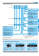
LEMO HEADQUARTERS SWITZERLAND LEMO SA Chemin des Champs-Courbes 28 - P.O. Box 194 - CH-1024 Ecublens Tel. (+41 21) 695 16 00 - Fax (+41 21) 695 16 02 - e-mail: info@lemo.com SUBSIDIARIES AUSTRIA LEMO Elektronik GesmbH Lemböckgasse 49/E6-3 1230 Wien Tel: (+43 1) 914 23 20 0 Fax:(+43 1) 914 23 20 11 sales@lemo.at JAPAN LEMO Japan Ltd 2-7-22, Mita, Minato-ku, Tokyo, 108-0073 Tel: (+81 3) 54 46 55 10 Fax: (+81 3) 54 46 55 11 lemoinfo@lemo.co.jp BRAZIL LEMO Latin America Ltda Av.