
Datasheet

Page 3/3
110214/10 LEM reserves the right to carry out modications on its transducers, in order to improve them, without prior notice www.lem.com
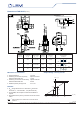
Number of
primary turns
Primary nominal
current rms
I
PN
[ A ]
Nominal
1)
output voltage
V
OUT
[ V ]
Primary
resistance
R
P
[ mW ]
Primary insertion
inductance
L
P
[ µH ]
Recommended
connections
1 ± 25 2.5 ± 0.625 0.18 0.013
6 5 4 OUT
IN 1 2 3
2 ± 12 2.5 ± 0.600 0.81 0.05
6 5 4 OUT
IN 1 2 3
3 ± 8 2.5 ± 0.600 1.62 0.12
6 5 4 OUT
IN 1 2 3
Dimensions LTSR 25-NP (in mm.)
Operation principle
Mechanical characteristics
● General tolerance ± 0.2 mm
● Fastening & connection of primary 6 pins 0.8 x 0.8 mm
Recommended PCB hole 1.3 mm
● Fastening & connection of secondary 4 pins 0.5 x 0.35 mm
Recommended PCB hole 0.8 mm
● Additional primary through-hole ∅ 3.2 mm
Remarks
● V
OUT
swings above the 2.5 V offset when I
P
ows from
terminals 1, 2, 3 to terminals 4, 5, 6 (with the arrow)
● For the EMC, the acceptance criteria are available on
request
● Temperature of the primary conductor should not exceed
100°C.
Note:
1)
Output voltage when LTSR 25-NP is used with internal
reference.
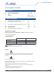
Output Voltage - Primary Current
- I
PM
- I
PN
I
PM
I
PN
0
V
OUT
[
V
]
[
At
]
I
P
4.5
5
2.5
3.125
0.5
1.875