
Data Sheet

Instruction of LS-FOG-01 Series Uniaxial Optical Fiber Gyroscope V1.0
2018-04-24 深圳市镭神智能系统有限公司 8 / 11
Leishen Intelligent System Co.,LTD.
9
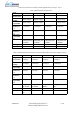
SEL+
Gyro strobe power supply
Note: Gyro strobe power is connected to +5V and the strobe signal is TTL level.
Note: When connecting or contacting the product, please take anti-static precautions according
to GJB1649-1993.
2.6.3 Form of output signal
The form of output signal of the product is RS422, Fiber Gyroscope communication controlled by
gyro strobe signal,This signal is TTL level,Low level effective,Pulse width not less than 10us,
Drive Electric current not less than 10mA,Gyro processing circuit should use optocoupler to
receive。The gyro processing circuit begins to send gyro data in the cycle through the serial
interface within 5 us after the falling edge of the gyro strobe pulse signal arrives.
2.6.4 Communication Protocol
The communication protocol is as follows: using RS-422 serial interface, the baud rate is
614.4kbps, and the communication frame character format: 1 start bit, 8 data bits, 1 stop bit, no
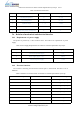
parity, and the communication cycle is 1ms~ 10ms. The data definition is shown in Table 4 below.
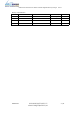
Table 4 Definition of Data
Byte S/N
Name
Contents
1
Frame header
99H
2
Frame header
66H
3
Status
-
4
~
6
Gyro Data
-
7
~
8
Gyro temperature
-
9
Checksum
-
Note 1: The status of the normal output of the gyroscope is A5H.
Note 2: The checksum is the lower 8 bits of the status flag and the result of the accumulation of
all bytes of the packet.
Note 3: The temperature data divided by 16 is the actual measured temperature value.
3 Assembly and Disassembly
3.1 Requirements