
Install Manual
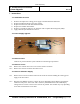
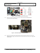
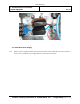
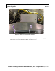
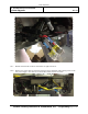
Table Of Contents
- 1. Purpose
- 2. Scope
- 3. Applicable Documents
- 4. Definitions
- 5. Requirements
- 6. Responsibilities
- 7. Instructions
- 7.1. Installation Overview
- 1. Remove and replace the existing power supply in the PV2 Electrical Enclosure.
- 2. Replace the Blueman decal on the outer radome.
- 3. Replace the PV2 masts with PV3 wideband masts.
- 4. Replace the V2ISUs with V3ISUs.
- 5. Replace or upgrade the ASCU to an ASCU VI with a Graphics Processing Unit (GPU).
- 6. Apply labels for system ID & FCC Part 15.
- 7.2. Power Supply Upgrade
- 7.3. Remove Power
- 7.4. Remove Covers
- 7.5. Remove Old Power Supply
- 7.5.1 Remove the four screws from the bottom of the electrical enclosure holding the existing power supply to the sheet metal.
- 7.5.2 Disconnect the Minifit connector at J26 on the power distribution board. Remove the 48 VDC conductors from pins 1 and 2 of the cable connector [1200-26805-00 or 1200-12288-00] by cutting with wire cutters as close to the connector as possibl...
- 7.5.3 Disconnect the Power Supply input AC power cables at the Power Distribution Block [1200-12283-00 & 1200-12284-00.]
- 7.5.4 Disconnect the ground cable [1200-12294-00] from the ground stud. Remove the four screws holding the power supply to the bottom of the electrical enclosure then remove power supply and attached cables.
- 7.6. Install New Power Supply
- 7.6.1 Slide new power supply assembly into electrical enclosure and re-install the four screws removed in step 7.5.1 to attach the power supply bracket to the electrical enclosure.
- 7.6.2 Insert the AC Line In [1200-32101-00] and Neutral [1200-32103-00] cables into the appropriate location on the AC in Power Distribution Block and tighten the lugs.
- 7.6.3 Attach both ground cables [1200-32102-00] to the ground lug.
- 7.6.4 Plug the 24VDC cable [1200-32104-00] from the Power Supply Assembly into J26 on the Power Distribution Board.
- 7.6.5 Using the existing 48VDC distribution cable removed from the connector in step 7.4.2. [1200-26805-00 or 1200-12288-00], strip back the insulation 10-mm ± 1-mm.
- 7.6.6 Carefully insert ends of the cables cut from the connector in step 7.4.2 into the terminals included with the Power Supply Assembly [1000-30982-00]. Insert the +48V cable (red) into the terminal labeled (+48V) and the -48V cable (black) int...
- 7.6.7 Double check that all electrical connections are tight and correct.
- 7.6.8 Remove two of the cable ties from the old power supply and attach with existing screws to the new power supply. Use cable ties to dress cables in the electrical enclosure.
- 7.7. Replace Covers and test functionality
- 7.8. Blueman Replacement
- 7.9. Remove existing decal
- 7.10. Mast Replacement
- 7.11. ISU Replacement
- 7.11.3 Plug the mast cables in by identifying the marking on each cable with the port markings on the enclosure.
- 7.11.4 With the V3ISU loosely installed, lift up the rear and place the cable retention bracket (P/N 3000-34233-00) under the cables while being careful not to disengage the cables. With the cables installed, gently slide the retention bracket int...
- 7.11.5 With the cable retention bracket in position, set the enclosure down on the tray and loosely install the common mounting screw from underneath to hold the retention bracket. Continue to loosely install the remaining two screws. Do not overt...
- 7.11.6 Apply pressure evenly to the front of the V3ISU to position the unit as far back and as far down as possible within the mounting tray. The two outermost mounting points will provide the limit of how far the unit will go in this direction. T...
- 7.11.7 On the rear of the ISU, push the retention bracket against the unit by applying pressure to the ends while tightening the screw as shown in Figure 27.
- 7.11.8 Snap fit a ferrite core P/N 0375-35639-00 on each individual cable (10X) and position them toward the cable retention bracket as shown in Figure 10. Once this has been completed the ISU tray can be rotated to the closed position and secured...
- 7.11.9 Dress the mast cabling as neatly as possible as shown in Figure 11 to assure there is no interference upon rotation of the mast.
- 7.11.10 Repeat steps 1 thru 7 and step 9 to replace the second ISU.
- 7.12. ASCU Upgrade
- 7.13. PV3 System Upgrade Labeling
- 8. Records

Leidos Proprietary
IP, ProVision2 to ProVision3
System Upgrade
8000-35512-IP
Rev A1
Leidos Security Detection & Automation, Inc. – Proprietary Page 3 of 26
7. Instructions
7.1. Installation Overview
1. Remove and replace the existing power supply in the PV2 Electrical Enclosure.
2. Replace the Blueman decal on the outer radome.
3. Replace the PV2 masts with PV3 wideband masts.
4. Replace the V2ISUs with V3ISUs.
5. Replace or upgrade the ASCU to an ASCU VI with a Graphics Processing Unit (GPU).
6. Apply labels for system ID & FCC Part 15.
7.2. Power Supply Upgrade
Figure 1 – New Power Supply Assembly [1000-30982-00]
7.3. Remove Power
Remove all power from PV2 system and follow Lockout/Tagout procedures.
7.4. Remove Covers
7.4.1 Remove the cosmetic skin covers to access the electrical enclosure.
7.4.2 Remove the electrical enclosure sheet metal cover.
7.5. Remove Old Power Supply
7.5.1 Remove the four screws from the bottom of the electrical enclosure holding the existing power
supply to the sheet metal.
7.5.2 Disconnect the Minifit connector at J26 on the power distribution board. Remove the 48 VDC
conductors from pins 1 and 2 of the cable connector [1200-26805-00 or 1200-12288-00] by
cutting with wire cutters as close to the connector as possible. Part number may vary depending
on the date of manufacture for the PV2.