20 30 40 50 Laser Locator Operating Instructions Laser Locator / Laser Locator Plus English Version 1.
Laser Locator Congratulations on purchasing your Laser Locator. Laser Locator = 4 instruments in 1: The object is marked by a red square that appears at the centre of the field of vision when you press one of the two measurement keys. • Binoculars Superb optics in a robust, watertight, rubber-armoured casing. • Digital Compass Displays magnetic azimuth or grid azimuth in degrees, gon or mils.
Contents Getting started ___________________________________________________________ 6 Changing the battery __________________________________________________ 6 Adjusting the neck strap _______________________________________________ 7 Removing the neck strap _______________________________________________ 7 Storing the Laser Locator ______________________________________________ 7 Eyepiece viewing distance ______________________________________________ 8 Eye-base adjustment ________________________________
Contents Azimuth and inclination measurement _______________________________________ 17 Factors influencing azimuth accuracy ____________________________________ 17 Azimuth measurement ________________________________________________ 18 Combined azimuth and inclination angle measurement ______________________ 19 Azimuth and distance between two objects ________________________________ 20 Relative horizontal and vertical angle ____________________________________ 21 Data transfer ____________________________
Contents Declination setting / correction __________________________________________ 28 Compass calibration _________________________________________________ 29 General instructions __________________________________________________ 29 Operator guidance ___________________________________________________ 30 Calibration procedure ________________________________________________ 31 Troubleshooting _________________________________________________________ 33 Safety notices _____________________________________
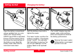
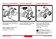
Getting started Open the battery compartment using a suitable tool, or a coin. Insert a 6V lithium battery, SANYO type 2CR5 or equivalent. Ensure that the drawing ribbon lies above the securing tape of the battery cover. Keep the battery cover seals and the instrument case clean. Getting started Changing the battery Refit the battery cover and retighten the screw. The Laser Locator monitors the battery’s condition. If the display shows ”LobAtt”, this indicates that the battery is used up.
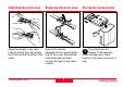
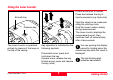
Adjusting the neck strap Removing the neck strap Storing the Laser Locator Adjust the length of the neck strap by pulling the strap slowly but firmly around the back of the catch. Open both catches: Squeeze the two clips together and lift the cover. Remove the strap ends and pull them through the lugs on the Laser Locator. To protect from dirt: Always fit the eyepiece cover and keep your Laser Locator in its pouch when not in use. Laser Locator-1.
Eyepiece viewing distance Eye-base adjustment + Dioptric adjustment + + + - When using the Laser Locator with glasses, push the eyecups fully inwards. Turn the adjusting knob until the left and right fields of view fuse to form a circular image. When using the Laser Locator without glasses, pull the eyecups out to the stop. Getting started - Sight on an object farther than 100 m away and rotate the eyepieces to obtain a sharp image. Standard setting: 0 dioptres.
Using the Laser Locator Double arrow plus a number: Press and release the key in rapid succession (e.g. triple click) Azimuth key 3x Distance key The Laser Locator is operated entirely by means of the keys on the top of the casing. Key operation is indicated by the following symbols: Downward arrow: press and hold down the key. Upward arrow: release the key Double arrow: press and release the key (click) Laser Locator-1.0 en 9 Sight the object to be measured using the pointing circle.
Distance measurements Factors affecting measurement range Reflective properties Size of the target Atmospheric conditions Vibration Distance measurements Oblique surfaces Lighting conditions 10 Laser Locator-1.
Distance measurement (slope distance) Press and hold the distance key; the pointing circle appears in the field of view. Sight the pointing circle on the object. Hold the Laser Locator steady as you release the distance key. Read off the distance. If "----" appears in the display, the object lies outside the measuring range, or measuring conditions are poor (see page 10). i Laser Locator-1.
Multiple object measurement Up to 3 separate distances can be obtained with a single measurement, for example when: - the laser beam passes through objects in front of the main target (bushes, shrubs, etc.) - there are reflective objects behind the main target (mountains, etc.) Distance measurements To use this feature, ”3diS on” (3 distances) must be activated via the configuration menu; see page 25. i Sight on the most visible portion of the object.
Combined measurement with data transfer (distance, azimuth, inclination) Measurement data is transmitted via the (optional) interface cable immediately after the measurement is taken (see page 22). It is not possible to store measurement data in the Laser Locator itself. Laser Locator-1.0 en Hold down both keys simultaneously; the pointing circle appears, together with the current azimuth. Sight the object with the pointing circle. Release both keys while holding the Laser Locator steady.
Horizontal dist. and height difference between your position and a remote object Click the distance key once, then press and hold it down. The pointing circle appears. Sight the object with the pointing circle. Release the distance key while holding the Laser Locator steady. The horizontal distance appears at the left and the height difference at the right of the field of view. i Distance measurements 14 Setting measurement units: see page 26. Laser Locator-1.
Distance between two objects Press and hold the distance key. The pointing circle appears. Sight the first object with the pointing circle. Click the azimuth key while holding the Laser Locator steady. The first object measurement is confirmed (1-P = first point). Sight the second object with the pointing circle. Release the distance key while holding the Laser Locator steady. The distance between the two objects is displayed. i Laser Locator-1.0 en 15 Setting measurement units: see page 26.
Horizontal and vertical distance between two objects Click the distance key once, then immediately press and hold it down. The pointing circle appears. Sight the first object with the pointing circle. Click the azimuth key while holding the Laser Locator steady. The first object measurement is confirmed (1-P = first point). Sight the second object with the pointing circle. Release the distance key while holding the Laser Locator steady.
Azimuth and inclination measurement Factors influencing azimuth accuracy The Laser Locator has a digital compass that works similarly to a magnetic compass. Metal objects and magnetic fields can cause errors in directional readings. Nonmagnetic metals and alloys do not affect the compass readings. 55 m 10 m Countermeasures: Calibrate the compass (see pages 30–32) after every battery change.
Azimuth measurement Press and hold the azimuth key. The pointing circle appears, together with the current azimuth. The display updates twice per second. Sight the object with the pointing circle, then release the azimuth key while holding the Laser Locator steady. The most recently measured azimuth is displayed. Azimuth and inclination measurement 18 i Setting measurement units: see page 26. Laser Locator-1.
Combined azimuth and inclination angle measurement Click the azimuth key once, then immediately press and hold it down. Laser Locator-1.0 en The following items appear in the field of view: - the pointing circle - the current azimuth at the left - the current angle of inclination at the right. Sight the object with the pointing circle, then release the azimuth key while holding the Laser Locator steady. 19 The azimuth and angle of inclination to the object are displayed.
Azimuth and distance between two objects Press and hold the azimuth key. The pointing circle appears, together with the current azimuth. Sight the first object with the pointing circle. Click the distance key (> 0.5 s) while holding the Laser Locator steady. The first object measurement is confirmed (1-P = first point). Sight the second object with the pointing circle. Release the azimuth key while holding the Laser Locator steady.
Relative horizontal and vertical angle Click the azimuth key once, then immediately press and hold it down. The following items appear in the field of view: - the pointing circle - the current azimuth at the left - the current angle of inclination at the right Laser Locator-1.0 en Sight the first object with the pointing circle. Click the distance key while holding the Laser Locator steady. Both angles are set to zero. Sight the second object and release the azimuth key.
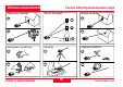
Data transfer Connecting / disconnecting the interface cable On the underside of the Laser Locators is a socket for sending data to: - personal computers or laptops - modems - fire control systems Our customer service will be pleased to inform you about special accessories for transmitting and analysing data. i Caution Incorrect handling can damage the socket and optional interface cable. Data transfer Lemo plug To plug: Align the respective red markings on the Lemo plug and socket.
Cable configuration AZI DIST GND SDS_IN SDS_OUT 1 2 3 4 5 Interface parameters ws rt sw gn bl 9 8 7 6 5 4 3 2 1 Interface ......................... RS 232 Data transmission ........ unidirectional Baud rate .................... 1200 bps Parity .................................. none Data bits ................................... 8 Stop bits ................................... 1 Handshake ......................... none 3m Lemo plug FHB.0B.305.
Data transfer format End character A complete set of measurements therefore consists of 30 ASCII characters. Before and after this continuous string, a steady logic 1 is transmitted while the Laser Locator is powered on. Data transfer Measurement examples: 0/5'236 ° XY Checksum XXXXXX Measurement value Start character Z Start character for measurement value: d ................................... distance a .................................... azimuth e ...................
Configuration Measuring 3 distances 5x 5x Click the distance key five times in rapid succession. The configuration settings appear in the field of view. The function "3dIS on" allows up to 3 distances to be displayed from a single measurement (see page 12). In the following configuration menue the multiple object measurement "3dIS" (3 Distances) can be switched on or off. Click the azimuth key until the desired function status for "3dIS" appears (function on or OFF). Laser Locator-1.
Settings Setting the measurement units 5x 5x Various angle and distance measurement units may be set via the configuration menu. Click the azimuth key five times in rapid succession. "Unit SEtt" appears briefly, followed by the measurement units currently in use by the Laser Locator. Settings Click the distance key until the desired units appear in the field of view: - at the left: angular unit in mils, gon or degrees - at the right: distance unit in metres (SI-Unit), yards, or feet.
Declination compensation Declination display Declination represents the deviation between magnetic north and grid north. Declination is displayed in the currently selected angular units (see page 26). Declination - varies from location to location - varies from time to time - is specified on most land and sea maps The stored declination value - is reset to 0 when the measurement units are changed (see page 26); - is retained when the battery is exhausted or replaced; - is factory-set to 0.
Declination setting / correction 3x 3x Click the azimuth key three times in rapid succession. The stored declination value is displayed. Settings Distance key - short click: the declination value increments by one unit; - long click (hold down the key for longer than half a second): the declination value decrements by one unit. 28 Click the azimuth key three times in rapid succession to store the new declination value.
Compass calibration General instructions How? When? Where? There is a choice of two calibration procedures: After every battery change. In an open area (e.g. a field) at an adequate distance from buildings and metallic objects (see page 17). Ensure that there are no buried pipes, cables, etc. in the vicinity. • 4 point calibration (4 Pt Co) achieves adequate precision for most applications. • 12 point calibration (12 Pt Co) is performed at the factory under optimal conditions. Laser Locator-1.
Operator guidance turn UP rot 90° +2 0° ( r tr o nh (un ri) Settings tilt ) -20° -20° turn dn The Laser Locator needs to be swivelled in various directions during calibration. Instructions for the required direction of movement appear successively in the display: turn UP .................... tilt upwards rtrn hori ....... return to horizontal turn dn ................. tilt downwards rot 90° ................... rotate by 90° do (tilt left) tilt left .......
Calibration procedure 4x Point the Laser Locator roughly northwards. Click the azimuth key four times in rapid succession. "FIEL Co" appears briefly, followed by "4 Pt Co" for the regular 4 point calibration. Laser Locator-1.0 en Only click the distance key if you want to perform the special 12 point calibration. "12 Pt Co" is displayed. i The selected calibration procedure begins in a few moments. Move the Laser Locator according to the displayed instructions.
Calibration procedure (continued) After 12 point calibration, the Laser Locator can be put down as soon as the pointing circle starts blinking. You can check the results later by clicking the azimuth key. i Magnetic interference can still lead to inaccurate measurements, even if calibration was successful. For this reason, you should verify compass accuracy after a successful calibration: perform several azimuth measurements on known landmarks and compare the results.
Troubleshooting Problem You cannot see a circular image with both eyes. Measurements cannot be taken. Laser Locator-1.0 en Possible cause Solution Eye-base or eyecup incorrectly adjusted. Adjust the eye-base or eyecup following the instructions on page 8. Eyes are not positioned on the Laser Locator’s optical axis. Reposition your head, or the instrument. The battery has run out. Replace the battery. Preferably use SANYO type. Battery contacts corroded. Clean the battery contacts.
Troubleshooting (continued) Problem "- - - -" appears in the display when distance is measured. Troubleshooting Possible cause Solution The distance is outside the specified measuring range. See the specified measuring range on page 41. Inadequate reflectance: • object too small or inaccurately targeted; • The Laser Locator was shaken during measurement; • Bad weather conditions (haze, fog, turbulence). See the list of factors affecting measuring range on page 10. 34 Laser Locator-1.
Troubleshooting (continued) Problem Possible cause Solution Distance display blinks. Multiple object measurement is activated: ”3dIS on”. Click the distance key to display distances in succession (see page 12). The Laser Locator measures objects in front or behind the intended object (e.g. bushes -> object -> mountain). The Laser Locator only displays the distance to the most reflective object in the line of vision. Activate multiple object measurement: ”3dIS on” (see page 25).
Troubleshooting (continued) Problem Inaccurate azimuth measurement values. The expected display does not appear after clicking a key several times. Troubleshooting Possible cause Solution Incorrect declination value has been stored. Store the correct declination value (see page 28). Disruptive magnetic fields at the measuring position. See the factors affecting measurement accuracy on page 17. Calibration in an area with magnetic interference. Recalibrate the compass (see pages 29-32).
Troubleshooting (continued) Problem ”Lo bAtt” is displayed. Laser Locator-1.0 en Possible cause Solution The battery is used up. You can still get some readings, but the battery needs to be replaced soon. Reduced battery performance at low temperature. You can still get some readings, but the Laser Locator or the battery needs to be warmed up (e.g. on your body).
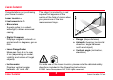
Safety notices Intended purpose The Laser Locator - is designed as a navigation aid; - is to be used in addition to other instruments or techniques; - must never be used as a sole navigation instrument. Limitations of use The Laser Locator must not be used in the vicinity of sensitive electrical equipment. All other usage limitations are mentioned in the technical specifications.
Safety notices (continued) Physical injury hazard • Do not place the Laser Locator on a vehicle parcel-shelf or dashboard – risk of injury when braking. • Check the carrying strap at regular intervals, and replace it if damaged. Environmental hazard The Laser Locator contains certain components that should be treated as hazardous waste, and must therefore be disposed of via a specialist dealer. Deposit used batteries at a proper collection point. Laser Locator-1.
Care / cleaning The Laser Locator’s performance and serviceability are conditional on regular care and immediate attention to problems: • Do not touch glass lenses with fingers. • Do not soil the operating keys with oil or grease. • Avoid abrupt temperature transitions, since these can cause condensation moisture to develop inside the Laser Locator. Therefore - do not use any kind of impregnated cloth intended for cleaning spectacle lenses, - do not use any solvent except water, e.g.
Technical data Optics Rangefinder Magnification ......................... 7x Clear objective diameter .. 42 mm Exit pupil diameter ............ 6 mm Eye relief ...................... 18,5 mm Field of view @ 1000 metres ................ 120 m Axial resolution ......... better than 6 arcseconds Interpupillary distance adjustment .......... 58,5-71,5 mm Focus ................................. fixed Dioptric correction ........ > ±4 dpt Laser type: IR diode ........ 860 nm Eye safety ........................
Technical data (continued) Magnetic compass (azimuth and inclination) Miscellaneous Azimuth measurement range .................................. 360° Accuracy (1σ): Azimuth ......................... ± 10 mil Inclination ....................... ± 3 mil Display resolution ........ 10 mil /1°/ 1 gon Maximum inclination / bank angle ........................ ± 45° Compass calibration ........... user initiated, menu driven Declination .......... ± 99° / 990 mil (adjustable) Power supply ......................
Equipment Shipping inventory SVP240 SEB50 STR1 SEV48 Order no. ––– 535 314 636 895 636 965 Description Laser Locator / Laser Locator Plus SEB50 lithium battery, 6 volt, SANYO type 2CR5 SVP240 grey pouch with accessories STR1 neck strap Optional equipment: 706 271 SEV48 interface cable, shielded, 3 m long 722 804 GEV154 interface cable to GPS Laser Locator-1.
Customer service Our customer and information service will be glad to offer assistance if your instrument requires maintenance, if it sustains damage, or if you require any other information: Leica Geosystems AG Defense & Special Projects Heinrich-Wild-Strasse CH-9435 Heerbrugg (Switzerland) Quality system Copyright SQS certification attests that Leica Geosystems AG Heerbrugg operates a quality management system that complies with international standards for quality and quality management systems (ISO 90
Eye safety IEC 825-1 (1990 / 1993) EN 60825 (1991 / 1994) ANSI Z 136.1 (1993) FDA 21 CFR Ch 1§ 1040 (1988) CLASS 1 LASER PRODUCT Laser Locator-1.
725351-1.0 en SW 1.4 Printed in Switzerland Copyright by Leica Geosystems AG Heerbrugg, Switzerland 2001 Translation of original text (724805-1.0 de SW 1.4) Leica Geosystems AG Defense & Special Projects CH-9435 Heerbrugg (Switzerland) Telephone +41 71 727 31 31 Fax +41 71 727 46 79 www.leica-geosystems.