
Owner's manual


Assembly Instru
ction
49
0
-
8
9
10 CRIB DRAWER
Page
2
of
5
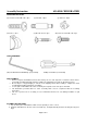
HARDWARE ENCLOSED:
(H
) Hex bolt screw
s
: M6 x
2
0
–
2
pcs
(K
)
Caster
–
4
pcs
TOOLS REQUIRED:
(M)
Hex Allen Wrench with Ball
tip
-
1pc (
I
ncluded)
Phillips Screwdriver (not included)
PRE
-
ASSEMBLY:
Remove all parts and hardware from the box and lay out on a clear carpeted or scratch
-
free work surface,
as this will a
void damaging parts during assembly. The shipping box provides an ideal work surface.
Do not dispose of any packaging or contents of the shipping carton until assembly is completed to avoid
accidentally discarding small parts or hardware.
Use the parts an
d hardware lists above to identify and separate each of the pieces included.
The illustrations provided allow for easier assembly when used in conjunction with the assembly
instructions.
The use of power tools for assembly is not recommended. Power tools
can damage hardware or split
wood.
ASSEMBLY INSTRUCTIONS:
1.
Lay out all the parts and hardware. Make sure the quantity of each
is
correct
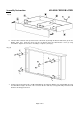
2.
Install
the
Cam B
olts into the
hole of the
Front
Side
(A)
, the
Right
Side
(D
)
and the
Left S
ide
p
anel
(C).
(See
Fig
1)
(I) Cam bolt
-
1
0pc
s
(J
) Cam nut
-
1
0pc
s
(L) Wooden Screw
-
8
pc
s
(N) Hex bolt
screw
s
M6 x 20
-
4
pc
s