
Manual

P52 DC BUS VOLTAGE
This displays the DC bus voltage in percent of nominal. Nominal DC bus voltage is determined by
multiplying the drive’s nameplate input voltage rating by 1.4.
P53 MOTOR VOLTAGE
This displays the output voltage in percent of the drive’s nameplate output voltage rating.
P54 MOTOR LOAD
This displays the motor load in percent of the drive’s output current rating.
P55 0-10 VDC ANALOG INPUT
This displays the level of the 0-10 VDC analog input signal at TB-5. A reading of 100%
indicates a 10 VDC input at TB-5.
P56 4-20 mA ANALOG INPUT
This displays the level of the 4-20 mA analog input signal at TB-25. A reading of 20% indicates a 4 mA
input at TB-25, and a reading of 100% indicates a 20 mA input at TB-25.
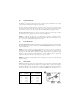
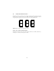
P57 TERMINAL STRIP STATUS
This indicates that status of several terminals using the vertical segments of the LED display. An
illuminated segment indicates that the particular terminal is closed with respect to TB-2. The CHARGE
RELAY is not a terminal, and should always be illuminated. See the diagram below:
45