
Manual


31
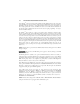
15.0 DESCRIPTION OF PARAMETERS
P01 LINE VOLTAGE SELECTION
This calibrates the drive for the actual applied input voltage, and can be set to HIGH (01) or LOW (02).
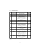
Refer to the table below for the proper setting depending on the input voltage.
RATED INPUT INPUT APPLIED INPUT PARAMETER
VOLTAGE PHASE VOLTAGE SETTING
120/208/240 Vac 1 110 - 120 Vac or 220 - 240 Vac HIGH (01)
1 200 - 208 Vac LOW (02)
208 / 240 Vac 1 or 3 220 - 240 Vac HIGH (01)
1 or 3 220 - 203 Vac LOW (02)
208 / 240 Vac 3 220 - 240 Vac HIGH (01)
3 200 - 208 Vac LOW (02)
400 / 480 Vac 3 440 - 480 Vac HIGH (01)
3 380 - 415 Vac LOW (02)
480 / 590 Vac 3 575 - 600 Vac HIGH (01)
3 460 - 480 Vac LOW (02)
NOTE: If this parameter is changed while the drive is running, the new value will not take effect until
the drive is stopped.
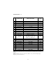
P02 CARRIER FREQUENCY
This sets the switching rate of the output IGBT’s. Increasing the carrier frequency will result in less
audible motor noise. Available settings are: 4 kHz, 6 kHz, 8 kHz, and 10 kHz.
PARAMETER CARRIER MAXIMUM OUTPUT AMBIENT OR OUTPUT
SETTING FREQUENCY FREQUENCY (NOTE 1) DERATE (NOTE 2)
01 4 kHz 240.0 Hz (400.0 Hz) 50 C or 100 %
02 6 kHz 240.0 Hz (600.0 Hz) 50 C or 100 %
03 8 kHz 240.0 Hz (999.9 Hz) 43 C or 92 %
04 10 kHz 240.0 Hz (999.9 Hz) 35 C or 82 %
NOTE 1: For drives with the High Output Frequency option, the carrier frequency also
determines the maximum output frequency (shown in parenthesis).
NOTE 2: The SM-Plus
™
drive is fully rated up to 6 kHz carrier frequency. If the 8 kHz or 10 kHz
carrier frequency is selected, the drive’s ambient temperature rating OR output current rating must be
derated to the value shown in the table above.