
Manual

19
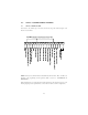
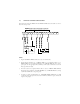
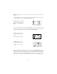
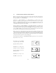
11.3 ALTERNATE TWO-WIRE START/STOP CONTROL
Shown below is the wiring diagram for an alternate two-wire start/stop control scheme, using one
maintained contact for RUN FORWARD and another maintained contact for RUN REVERSE.
NOTES:
1. For this control scheme, TB-13A MUST be set to RUN REVERSE (05), even if REVERSE
direction is not required. Refer to Parameter 10 - TB13A FUNCTION.
2. Close TB-12 to TB-2 to RUN and open TB-12 to TB-2 to STOP.
3. If reverse direction is also required, ROTATION DIRECTION (Parameter 17) must be set to
FORWARD AND REVERSE (02). Close TB-13A to TB-2 to RUN in REVERSE, and open
TB-13A to TB-2 to STOP. If TB-12 and TB-13A are closed to TB-2, the drive will STOP.
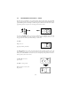
4. For 0-10 VDC or 4-20 mA speed control, use one of the following methods:
1. Program one of the TB-13 terminals (13A, 13B, or 13C) for 0-10 VDC (02) or 4-20 mA
(03). When that TB-13 terminal is closed to TB-2, the drive will respond to the selected speed
reference signal. If that TB-13 terminal is not closed to TB-2, the drive will respond to the
speed control source selected in Parameter 05 - STANDARD SPEED SOURCE. This
method must be used if it is necessary to toggle between two speed sources.
2. Program Parameter 05 - STANDARD SPEED SOURCE for 0-10 VDC (03) or 4-20 mA
(04). This method is preferable if only one speed source is required, as this method leaves the
TB-13 terminals free to be used for other functions.