TM SPEEDMASTER Variable Speed D.C. Control INSTRUCTION MANUAL This Book Covers Speedmaster Control Numbers 174902 & 174903 TM LEESON ELECTRIC CORPORATION GRAFTON, WI 53024-0241 U.S.A.
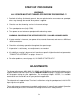
TABLE OF CONTENTS WARRANTY ........................................................................................................................... 2 INTRODUCTION ..................................................................................................................... 3 COMMONLY ASKED QUESTIONS ....................................................................................... 3 CONTROL FEATURES ..............................................................................................
LIMITED WARRANTY A. WARRANTY: LEESON Electric Corporation warrants that their products will be free from defects in material and workmanship for a period of one (1) year from date of shipment thereof. Within the warranty period LEESON Electric will repair or replace such products which are returned to LEESON Electric or to the nearest Branch Office, with shipping charges prepaid. At our option, all return shipments are F.O.B. LEESON Electric or its Branch Office.
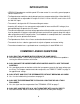
INTRODUCTION • LEESON'S Speedmaster variable speed DC motor control is a versatile, general purpose control rated to 2 HP. • The Speedmaster model has a dual voltage input (may accommodate either 120 or 240 VAC). It is available with an adjustable HP range of 1/8 thru 1 HP for 120 VAC, and 1/4 thru 2 HP for 240 VAC input. • The control is designed for DC Permanent Magnet motors.
CONTROL FEATURES MIN. SPEED (minimum speed) - Allows adjustment of the motor speed when the speedpot is set at minimum (CCW). This permits the user to eliminate the “deadband” on the main speed control permitting zero calibration. Clockwise rotation of “MIN” trimpot increases minimum motor speed. MAX. SPEED (maximum speed) - provides for adjustment of the motor speed when the speedpot is set at maximum (CW).
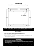
DIMENSIONS Allow 3.50" for height clearance, 7.40" for overall length. 7.000 5.500 .750 7/32 SLOTS (4) TYP. .350 DEEP 5.530 5.125 CAUTION: DO NOT MOUNT CONTROL WHERE AMBIENT TEMPERATURE IS OUT SIDE THE RANGE OF -10o C. (15o F.) TO 45o C. (115o F.) MOUNTING 1. Four 7/32" diameter slots are provided for control mounting. 2. The chassis of the control can be used as a template. 3. Use standard hardware to mount. 4.
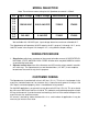
MODEL SELECTION Note: The minimum current rating for this Speedmaster control is 150mA. H.P. Input Voltage Output Voltage Unidirectional Reversing 1/8 1/4 1/3 1/2 3/4 1.0 120/240 VAC 0-90/0-180 VDC 174902 174903 1.5* 2.0* 240 VAC 0-180 VDC 174902 174903 * Not available with 120 VAC input - Input voltage determines maximum allowable H.P. The Speedmaster will operate a 90 VDC motor in the H.P. range of 1/8 through 1 H.P., and a 180 VDC motor in the range of 1/4 through 2 H.P.
TERMINAL STRIP WIRING The Speedmaster has an 11 position block type terminal strip for ease of connection. P1-1 (SPEEDPOT LO) Connects to low side (orange wire) of the 5K speedpot (normally the CCW end). This input is raised and lowered by the MIN. trimpot. Electronic speed input (voltage follower) may be referenced to speedpot LO if the MIN trimpot adjustments are to be active. Otherwise, inputs may be referenced to -ARM, which will bypass the MIN trimpot.
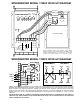
SPEEDMASTER MODEL 174902 HOOK-UP DIAGRAM Min Max I.R. Accel Comp HI (white) WIPER (red) LO (orange) Cur. Lim. DPST SWITCH SPEEDPOT (white) (black) (white) (black) Inhibit Pin P2 INSIDE OF COVER chassis ground Switched AC Switched AC AC -Field AC +Field +Arm Pot Hi -Arm Wiper Pot Lo P1 -1 -2 -3 -4 -5 -6 -7 -8 -9 -10 -11 field* motor armature ac input BEFORE SCREWING DOWN COVER ASSEMBLY, ROUTE WIRING THROUGH CONDUIT HOLES IN ENDPLATE BY TERMINAL STRIP.
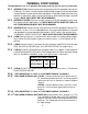
START-UP PROCEDURE WARNING: ALL POWER MUST BE TURNED OFF BEFORE PROCEEDING !!! 1. Recheck all wiring. Accidental grounds, loose or pinched wires on armature or speedpot wires may damage the control when power is applied. 2. Check to see that incoming service is of correct voltage. 3. Turn speedpot to zero (fully CCW). 4. Turn power on and advance speedpot while observing motor. WARNING: POWER MUST BE OFF BEFORE STEP 5 CAN BE ACCOMPLISHED! 5.
TRIMPOT ADJUSTMENT PROCEDURE TRIMPOT FUNCTION ADJUSTMENT MAX SETS MAXIMUM MOTOR SPEED when speedpot is set at maximum (100% rotation CW). CW rotation of MAX trimpot increases maximum motor speed. 1. TURN DRIVE POWER OFF!! 2. Connect DC Voltmeter: + to +ARM, - to -ARM. 3. Set meter voltage range: (90VDC or 180VDC). 4. Turn power on. Set speedpot at 100%. 5. Adjust MAX trimpot to rated motor armature voltage as shown on meter. NOTE: A tachometer or strobe may be used in lieu of a meter.
SPEEDMASTER TRIMPOT SETTING CHART * THESE SETTINGS APPLY WHEN USING A 5000 OHM MASTER SPEEDPOT. * THIS TRIMPOT CHART IS APPROXIMATE. USE IT IN CONJUNCTION WITH THE ADJUSTMENT PROCEDURES. MIN MIN MAX ACCEL I.R. MAX ACCEL I.R. C.L. C.L. H.P. INPUT VOLTAGE OUTPUT VOLTAGE 1/8 120VAC 0-90VDC 1/4 120VAC 0-90VDC 1/3 120VAC 0-90VDC 1/2 120VAC 0-90VDC 3/4 120VAC 0-90VDC 1.0 120VAC 0-90VDC H.P.
CONTROL MODIFICATIONS TWO SPEED OPERATION Two pot operation is done using two 10K ohm speed potentiometers in parallel (both HI's to P1-3, both LO's to P1-1). The WIPER is switched using a SPDT switch. DYNAMIC BRAKING A DPDT switch is used to inhibit the control and to connect the DBR. Typical values for the DBR (dynamic brake resistor) are 5 ohms for 120V, 10 ohms for 240V (both 35W to 50W). Note that motor horsepower, inertia, and cycle time effect sizing of the DBR.
SPEEDPOT DIMENSION INFORMATION CUSTOMER'S MOUNTING BRACKET DIALPLATE 2.00" dia. 1.240 .500 .370 SPEEDPOT KNOB .370 HEX NUT 1.250 .250 Dia. LOCK WASHER SPEEDPOT (5K 2W) O-RING .437 5/32 DIA. 3/8 DIA. SPEEDPOT LOCATOR HOLE DIMENSIONS MAINTENANCE PROCEDURE In normal operation this control needs no routine maintenance. The cover may be cleaned with a mild detergent. Solvent type of cleaners should not be used.
IN CASE OF DIFFICULTY If a newly installed control will not operate, it is possible that a terminal or connection is loose. Check to make sure that all connections are secure and correct.
SPECIFICATIONS AC input voltage ...................................................................... ±10% of rated line voltage Acceleration .......................................................................................... 0.5 to 8.0 seconds Amps - DC output .................................................................... 150 mA to 10.8 Amps D.C. Controller overload capacity ........................................................... 150% for one minute Current limit trimpot range ...........
SPEEDMASTER PARTS PLACEMENT & LIST RESISTORS R12 R22 R9 R23 C9 R28 R14 C7 R34 R30 R13 R11 R31 Q5 R21 D3 R16 C5 C4 C10 R6 R7 R32 C2 R5 R8 C6 R2 Q1 R4 Q2 R35 R17 R3 C8 C3 R26 R36 R20 R19 R27 H1 R25 JU2 D9 P2 D10 R1 JU1 D8 D2 D4 P1-2 Q6 F1 R37 C12 D1 C1 (dot on side towards fuse) GENTRON PKG.
% AC1 AC2 P1-10 SPEEDMASTER SCHEMATIC P1-11 A B F1 * HI P1-3 REMOTE SPEEDPOT R10 5K C9 .22uf 250V +12V +12V 9 4 10 R32 47K + 11 R30 180K 8 Q5-3 WIPER P1-2 - C11 .01uf 100V R34 100K R29 10K C10 .01uf 100V R31 390K % ACCEL R9 250K 6 SPARE P1-9 SPARE 6 + Q3 L512F Q2-2 3052 MOC 7 - R25 390 OHM R37 1 OHM C8 .0047uf 1KV R27 1K +12V R33 470K R36 91K R19 150K 17 +FIELD P1-6 D9 1N4005 D2 1N4005 C3 .
Bulletin #301 12/00 18