
Instruction Manual


9
Installation
SPEEDMASTER™ OPERATION MANUAL
SO501
INHIBIT
MIN SPD
ACCEL
T501
O
V502
R502
C503
SW501
230 - 115
TQ LIMIT
IR COMP
DECEL
MAX SPD
SO502
S3 S2 S1
SW502180 - 90
IC502C501
C504
R501
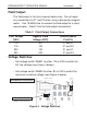
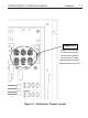
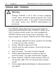
MAX ARMATURE VOLTAGE SWITCH
SW502 (90 or 180 VDC)
AC LINE VOLTAGE SWITCH
SW501 (115 or 230 VAC)
Figure 4. Voltage Switches
Voltage Switches
• Set voltage switch SW501 to either 115 or 230 to match the
AC line voltage (see Figure 4 below).
• Set voltage switch SW502 to either 90 or 180 to match the
maximum armature voltage (see Figure 4 below).
Field Output
The field output is for shunt wound motors only. Do not make
any connections to F1 and F2 when using a permanent magnet
motor. Use 18 AWG wire to connect the field output to a shunt
wound motor. Table 2 lists the field output connections.
Table 2. Field Output Connections
Line Voltage Approx. Field Connect Motor
(VAC) Voltage (VDC) Field To
115 50 F1 and L1
115 100 F1 and F2
230 100 F1 and L1
230 200 F1 and F2