® 174102, 174103 & 174107 NEMA 4X SCR MOTOR CONTROLS Operation Manual ® SPEEDMASTER
LIMITED WARRANTY A. Warranty - LEESON Electric warrants that its products will be free from defects in material and workmanship for a period of one (1) year from the date of shipment thereof. Within the warranty period, LEESON will repair or replace such products that are returned to LEESON or to the nearest Branch Office, with shipping charges prepaid. At our option, all return shipments are F.O.B. LEESON or its Branch Office.
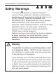
i SPEEDMASTER™ OPERATION MANUAL Safety Warnings • This symbol denotes an important safety tip or SHOCK HAZARD • • AVOID HEAT KEE DR OID ATION warning. Please read these instructions carefully before performing any of the procedures contained in this manual. DO NOT INSTALL, REMOVE, OR REWIRE THIS EQUIPMENT WITH POWER APPLIED. Have a qualified electrical technician install, adjust and service this equipment.
ii SPEEDMASTER™ OPERATION MANUAL Contents Warranty Statement Safety Warnings Inside Front Cover i Specifications 1 Dimensions 2 Overview 3 Installation 4 Mounting . . . . . . . . . . . . . . . . . . . . . . . . . . . . . . . . . . . . . . . . . . . . . . . .4 Removing the Plastic Cover . . . . . . . . . . . . . . . . . . . . . . . . . . . . . . . . . .4 Line fusing . . . . . . . . . . . . . . . . . . . . . . . . . . . . . . . . . . . . . . . . . . . . . . .4 Connections . . . . . . . . . . . . . .
SPEEDMASTER™ OPERATION MANUAL Contents 174103 . . . . . . . . . . . . . . . . . . . . . . . . . . . . . . . . . . . . . . . . . . . . . . . . .19 174107 . . . . . . . . . . . . . . . . . . . . . . . . . . . . . . . . . . . . . . . . . . . . . . . . .20 Application Notes 21 Inhibit circuit . . . . . . . . . . . . . . . . . . . . . . . . . . . . . . . . . . . . . . . . . . . . . . .21 Decelerating to minimum speed . . . . . . . . . . . . . . . . . . . . . . . . . . . . . . . .23 Dynamic Braking . . . . . .
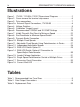
iv SPEEDMASTER™ OPERATION MANUAL Illustrations Figure Figure Figure Figure Figure Figure Figure Figure Figure Figure Figure Figure Figure Figure Figure Figure Figure Figure Figure 1. 174102, 174103 & 174107 Dimensional Diagrams . . . . . . . . . . . . .2 2. Cover removal for terminal strip access . . . . . . . . . . . . . . . . . . . . .6 3. Drive connections . . . . . . . . . . . . . . . . . . . . . . . . . . . . . . . . . . . . . .7 3a. External Signal Connections, 174103.00 . . . . . . . . . . . . . .
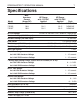
1 SPEEDMASTER™ OPERATION MANUAL Specifications Model 174102 174103 174107 Max. Armature Current (Amps DC) 10.0 10.0 10.0 AC Line Voltage HP Range with 115 VAC Applied 1/8–1 1/8–1 1/8–1 HP Range with 230 VAC Applied Style 1/4–2 NEMA 4X 1/4–2 NEMA 4X 1/4–2 NEMA 4X 115 VAC or 230 VAC ±10%, 50/60 Hz, single phase Armature Voltage (115 VAC Input) 0–90 VDC Armature Voltage (230 VAC Input) 0–180 VDC Form Factor 1.
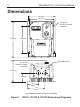
2 SPEEDMASTER™ OPERATION MANUAL Dimensions 5.63 [143] 5.16 [ 131] POWER ON 0.19 [5.00] SLOTTED HOLES 4 PLACES OFF ® SPEEDMASTER 5 4 6 3 7 2 8 1 9 1 0 0 7.50 [191] SPEED 5.50 [140] ® ADJUSTABLE SPEED DC MOTOR CONTROL BOTTOM PLATE 0.73 [18.5] CONDUIT HOLES 2 PLACES 4.56 [116] 2.12 [53.8] 2.20 [55.9] 3.40 [86.4] ALL DIMENSIONS IN INCHES [MILLIMETERS] Figure 1.
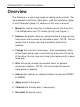
SPEEDMASTER™ OPERATION MANUAL 3 Overview The following is a quick-step guide to setting up the control. For more detailed installation information, read the Installation (page 4) and Calibration (page 10) sections of this user’s manual. 1. Mount the control using the 4 slotted holes on the heat sink. The slotted holes are 0.19 inches [5 mm] (see Figure 1). 2. Remove the plastic cover by unscrewing the 6 screws on the front cover and 5 screws on the bottom plate.
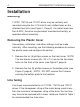
4 SPEEDMASTER™ OPERATION MANUAL Installation Mounting 174102, 174103 and 174107 drives may be vertically wall mounted using the four 0.19 inch (5 mm) slotted holes on the attached heat sink (see Figure 1, Page 2). For motor loads less than 5 ADC, the drive may be bench mounted horizontally, or operated without mounting. Removing the Plastic Cover Connections, calibration, and other settings must be made internally.
SPEEDMASTER™ OPERATION MANUAL Installation 5 Table 1. Recommended Line Fuse Sizes MOTOR HP FUSE SIZE (AMPS) @ 115 VAC INPUT FUSE SIZE (AMPS) @ 230 VAC INPUT 1/4 1/3 1/2 3/4 1 1 1/2 2 5 8 8 10 15 – – 3 3 5 8 8 10 15 Connections Warning Do not connect this equipment with power applied. Failure to heed this directive may result in fire or serious injury. 1. Install conduit hardware through the two 0.73” (18.
Installation SPEEDMASTER™ OPERATION MANUAL 1 2 POWER ON OFF ® SPEEDMASTER 1 8 9 2 3 7 4 5 6 0 0 3 1 6 4 SPEED ® ADJUSTABLE SPEED DC MOTOR CONTROL STEP #1 REMOVE THE SIX (6) PHILLIPS SCREWS ON THE FRONT CASE. NOTE: THE TWO SHORTER SCREWS (#6 - 32 x 2 ½) ON THE FRONT CASE ARE USED AT HOLE LOCATIONS 5 & 6. 6 5 CUSTOMER SUPPLIED WATERTIGHT CORD CONNECTORS (2) 1 STEP #2 REMOVE THE FIVE (5) PHILLIPS SCREWS ON THE BOTTOM PLATE.
SPEEDMASTER™ OPERATION MANUAL MO Installation MOV501 F502 L2 FRM SW L1 A2 TO SW A1 L2 TO SW L1 A2 FRM SW A1 F501 MOV503 A1 A2 L1 L2-230 L2-115 F2 F1 TB501 + 230 VAC 115 VAC EARTH GROUND (GREEN SCREW) FIELD OUTPUT LINE VOLTAGE INPUT (115 or 230 VAC) FIELD OUTPUT CONNECTIONS MOTOR ARMATURE The field output is for shunt wound motors only. Do not make any connections to F1 and F2 when using a permanent magnet motor. For field motor connections, see Table 2 on Page 9. Figure 3.
Installation SPEEDMASTER™ OPERATION MANUAL IC1 R9 3 R7 2 1 SIG MIN. R8 C4 SIG MAX P502 P501 SO501 PL501 DECEL TQ LIMIT ACCEL D501 C3 IR COMP D502 MIN. SPD R6 PCM CARD 8 MAX SPD R5 1 2 3 4 TB501 Q2 R1 RSH C2 RSH = 1000 OHM for 4 - 20 mA RSH = 250 OHM for 10 - 50 mA RSH = NOT USED for 1 - 5 mA RSH = NOT USED for 0 - 10V signal TERMINAL 2 + 0 - 10V SPEED ADJUST SIGNAL INPUT T501 C1 R3 Q1 R4 R2 TERMINAL 3 (-) COMMON Figure 3a. External Signal Connections For 174103.
SPEEDMASTER™ OPERATION MANUAL Installation Field Output The field output is for shunt wound motors only. Do not make any connections to F1 and F2 when using a permanent magnet motor. Use 18 AWG wire to connect the field output to a shunt wound motor. Table 2 lists the field output connections. Table 2. Field Output Connections Line Voltage (VAC) Approx.
10 SPEEDMASTER™ OPERATION MANUAL Calibration Warning Dangerous voltages exist on the drive when it is powered. When possible, disconnect the voltage input from the drive before adjusting the trimpots. If the trimpots must be adjusted with power applied, use insulated tools and the appropriate personal protection equipment. BE ALERT. High voltages can cause serious or fatal injury.
SPEEDMASTER™ OPERATION MANUAL IL502 11 CURRENT LIMIT IL501 SO501 IC502 SW502 INHIBIT C504 POWER IC501 Calibration TRIMMER POTS TORQUE LIMIT (TQ LIMIT) ACCELERATION (ACCEL) REGULATION (IR COMP) MINIMUM SPEED (MIN SPD) MAXIMUM SPEED (MAX SPD) C503 R502 R501 MOV502 DECELERATION (DECEL) DECEL S3 S2 S1 ACCEL SO502 TQ LIMIT F502 L2 FRM SW L1 A2 TO SW A1 A2 FRM SW A1 F501 TB501 Figure 5.
12 Calibration SPEEDMASTER™ OPERATION MANUAL Calibration procedure Calibrate the drive using the following procedure: 1. 2. 3. 4. 5. 6. Set the MIN SPD, IR COMP, ACCEL and DECEL trimpots to zero (full CCW). Set the TORQUE trimpot to maximum (full CW). Set the MAX SPD trimpot to midrange (approximate 12 o’clock position). Turn the speed adjust potentiometer on front cover to zero. Apply power to the drive.
SPEEDMASTER™ OPERATION MANUAL Calibration 13 MAXIMUM SPEED (MAX SPD) The MAX SPD setting determines the motor speed when the speed adjust potentiometer is turned full CW or reference signal is at its maximum. It is factory set for maximum rated speed. To calibrate, set the MAX SPD trimpot full CCW. Turn the speed adjust potentiometer full CW or reference signal to its maximum. Adjust the MAX SPD trimpot until the desired maximum motor speed is reached.
14 Calibration SPEEDMASTER™ OPERATION MANUAL TORQUE LIMIT (TORQUE) Warning Although TORQUE is set current rating, continuous may damage the motor. If the rating, contact your assistance. to 150% of drive nameplate operating beyond that rating you intend to operate beyond LEESON representative for The TORQUE setting determines the maximum torque for accelerating and driving the motor. TORQUE is factory set at 150% of maximum drive current.
SPEEDMASTER™ OPERATION MANUAL Calibration 15 8. Remove power from the drive. 9. Remove the lock from the motor shaft. 10. Remove the ammeter in series with the motor armature. ACCELERATION (ACCEL) The ACCEL setting determines the time the motor takes to ramp to a higher speed. See Specifications on page 1 for approximate acceleration times. The ACCEL setting is factory set to its minimum value (full CCW).
16 TORQUE Calibration IR COMP SPEEDMASTER™ OPERATION MANUAL 1 HP 90 VDC 1750 RPM 10 AMPS 2 HP 180 VDC 1750 RPM 9.2 AMPS 1/2 HP 90 VDC 1750 RPM 5 AMPS 1 HP 180 VDC 1750 RPM 5 AMPS 1/4 HP 90 VDC 1750 RPM 2.7 AMPS 1/2 HP 180 VDC 1750 RPM 1.3 AMPS TORQUE IR COMP Figure 6.
SPEEDMASTER™ OPERATION MANUAL 17 Operation Warning Change voltage switch settings only when the drive is disconnected from AC line voltage. Make sure both switches are set to their correct position. If the switches are improperly set to a lower voltage position, the motor will not run at full voltage. If the switches are improperly set to a higher voltage position, the motor will overspeed, which may cause motor damage.
18 Operation SPEEDMASTER™ OPERATION MANUAL Startup Warning If the motor or drive does not perform as described in this section, disconnect the AC line voltage immediately. Refer to Troubleshooting, page 34, for further assistance. 174102 1. Set the speed adjust potentiometer (SPEED dial) to “0”, or full CCW. 2. Apply AC line voltage. 3. Set the POWER switch to the ON position. 4. Slowly advance the speed adjust potentiometer CW. The motor slowly accelerates as the potentiometer is turned CW.
SPEEDMASTER™ OPERATION MANUAL Operation 19 174103 Manual Operation 1. Set the Signal/Manual Switch located on the enclosure to the MANUAL position. 2. Set the speed adjust dial to “0” (full CCW). 3. Apply AC line voltage 4. Set the POWER switch to the ON position 5. Slowly advance the speed adjust dial CW. The motor slowly accelerates as the dial is tunred CW. Continue until the desired speed is reached. 6.
20 SPEEDMASTER™ OPERATION MANUAL 174107 Warning Do not change the FORWARD / OFF / REVERSE switch while the motor is running. The motor must come to a complete stop before reversing. Changing motor direction before allowing the motor to completely stop will cause excessively high current to flow in the armature circuit, and may damage the drive and/or motor. 1. Set the FORWARD/OFF/REVERSE switch to the OFF position. 2. Set the speed adjust potentiometer (SPEED dial) to “0”, or full CCW. 3.
SPEEDMASTER™ OPERATION MANUAL 21 Application Notes Warning Decelerating to minimum speed, inhibit operation, or coasting to a stop is recommended for frequent starts and stops. Do not use any of these methods for emergency stopping. They may not stop a drive that is malfunctioning. Removing AC line power (both L1 and L2) is the only acceptable method for emergency stopping.
22 Application Notes RUN COAST TO MIN SPEED INH IBI T SO501 2-PIN HEADER Use LEESON accessory plug harness (part number: 900282.01) to mate with 2-pin header (SO501) on control board. Figure 7.
23 Application Notes Decelerating to minimum speed The switch shown in Figure 8 may be used to decelerate a motor to minimum speed. Closing the switch between S1 and S2 decelerates the motor from set speed to minimum speed determined by the MIN SPD trimpot setting. If the MIN SPD trimpot is set full CCW, the motor decelerates to zero speed when the switch between S1 and S2 is closed. The DECEL trimpot setting determines the rate at which the drive decelerates.
24 Application Notes Dynamic Braking Warning Wait for the motor to completely stop before switching it back to the RUN position. This will prevent high armature currents from damaging the motor or drive. Dynamic braking may be used to rapidly stop a motor (Figure 9, page 25). For the RUN/BRAKE switch, use a two-pole, twoposition switch rated for at least the maximum DC armature voltage and and maximum braking current.
25 Application Notes A1 A2 RUN MOTOR DYNAMIC BRAKE RESISTOR BRAKE DYNAMIC BRAKE RESISTOR 15 ohm for 90 VDC motors 30 ohm for 180 VDC motors INH IBI T SO501 2-PIN HEADER Use LEESON accessory plug harness (part number: 900282.01) to mate with 2-pin header (SO501) on control board. Figure 9.
26 Application Notes Multiple Fixed Speeds Replace the speed adjust potentiometer with series resistors with a total series resistance of 10K ohms (Figure 10). Add a single-pole, multi-position switch with the correct number of positions for the desired number of fixed speeds. R4 R3 R2 TOTAL SERIES RESISTANCE 10K OHMS S 3 S 2 S S 1 05 02 R1 SO502 3-PIN HEADER Use customer supplied Molex connector #09-50-3031 to mate with 3-pin header (SO502) on control board. Figure 10.
27 Application Notes Adjustable speeds using potentiometers in series Replace the speed adjust potentiometer with a single-pole, multiposition switch, and two or more potentiometers in series, with a total series resistance of 10K ohms. Figure 11 shows a connection for fixed high and low speed adjust potentiometers.
28 Application Notes Independent adjustable speeds Replace the speed adjust potentiometer with a single pole, multiposition switch, and two or more potentiometers in parallel, with a total parallel resistance of 10K ohms. Figure 12 shows the connection of two independent speed adjust potentiometers that can be mounted at two separate operating stations.
29 Application Notes RUN/JOG switch Using a RUN/JOG switch is recommended in applications where quick stopping is not needed and frequent jogging is required. Use a single pole, two position switch for the RUN/JOG switch, and a single pole, normally closed, momentary operated pushbutton for the JOG pushbutton. RUN/JOG option #1 In the first wiring option, connect the RUN/JOG switch and JOG pushbutton to the inhibit plug as shown in Figure 13.
30 Application Notes RUN/JOG option #2 In the second wiring option, connect the RUN/JOG switch and the JOG pushbutton as shown in Figure 14. When the RUN/JOG switch is set to JOG, the motor decelerates to minimum speed (minimum speed is determined by the MIN SPD trimpot setting). Press the JOG pushbutton to jog the motor. Return the RUN/JOG switch to RUN for normal operation.
31 Application Notes Leader-follower application In this application, use a 174335 Process Control Module (PCM) to monitor the speed of the leader motor (Figure 15). The PCM isolates the leader motor from the follower drive, and outputs a voltage proportional to the leader motor armature voltage. The follower drive uses this voltage reference to set the speed of the follower motor. An optional ratio potentiometer may be used to scale the PCM output voltage.
32 Application Notes Single speed potentiometer control of multiple drives Multiple drives can be controlled with a single speed adjust potentiometer using a 174335 Process Control Module (PCM) at the input of each drive to provide isolation (Figure 16). Optional ratio potentiometers can be used to scale the PCM output voltage, allowing independent control of each drive.
33 Application Notes Reversing A dynamic brake may be used when reversing the motor direction (Figure 17). Use a three-pole, three-position switch rated for at least the maximum DC armature voltage and maximum braking current. Wait for the motor to stop completely before switching it to either the forward or reverse direction. See the dynamic braking section, page 24, for recommended dynamic brake resistor sizes. NOTE: Model 174107 is equipped with the reversing feature, but not the dynamic brake feature.
34 SPEEDMASTER™ OPERATION MANUAL Troubleshooting Warning Dangerous voltages exist on the drive when it is powered. When possible, disconnect the drive while troubleshooting. High voltages can cause serious or fatal injury. Before troubleshooting Perform the following steps before starting any procedure in this section: • Disconnect AC line voltage from the drive. • Check the drive closely for damaged components.
35 Troubleshooting Power and Current Limit LEDs 174102, 174103 & 174107 drives are equipped with a green, PCB-mounted power LED and a red, PCB-mounted current limit LED. POWER LED (IL502) The green power LED turns on when AC line voltage is applied to the drive.
36 Troubleshooting Symptom Fuse blows or circuit breaker trips Line fuse does not blow or circuit breaker does not trip, but the motor does not run SPEEDMASTER™ OPERATION MANUAL Possible Causes Suggested Solutions 1. Line fuses or circuit breakers are the wrong size. 1. Check that line fuses or circuit breakers are the proper size. 2. Motor cable or armature is shorted to ground. 2. Check motor cable and armature for shorts. 3.
SPEEDMASTER™ OPERATION MANUAL Symptom Line fuse does not blow or circuit breaker does not trip, but the motor does not run (cont.) Possible Causes Troubleshooting 37 Suggested Solutions 3. Drive is in current limit. 3. Verify that the motor is not jammed. Increase TORQUE setting (page 14). 4. Drive is not receiving AC line voltage. 4. Apply AC line voltage to L1 and L2. 5. Motor is not connected. 5. Connect motor to A1 and A2. Motor runs too fast at maximum speed setting 1.
38 Troubleshooting Symptom Motor pulsates or surges under load SPEEDMASTER™ OPERATION MANUAL Possible Causes Suggested Solutions 1. IR COMP is set too high. 1. Adjust the IR COMP setting slightly CCW until the motor speed stabilizes (page 13). 2. Control is in current limit mode. 2. Check that motor is of sufficient horsepower and amperage. On non-reversing drives, motor runs in the opposite direction 1. Motor armature leads are reversed. 1. Reverse connections to the motor armature.
39 Troubleshooting Replacement Parts Table 3 is provided as a guide for some component parts that may require replacement. These items are not available from LEESON. They are readily available from suppliers of electronic components. Replacing these items on drives that are under warranty will void the warranty. Warning Dangerous voltages exist on the drive when it is powered. Disconnect power from the drive and allow time for the voltage on the capacitors to dissipate before working on the drive.
40 NOTES SPEEDMASTER™ OPERATION MANUAL
SPEEDMASTER™ OPERATION MANUAL NOTES 41
42 NOTES SPEEDMASTER™ OPERATION MANUAL
DISCLAIMER The information and technical data in this manual are subject to change without notice. LEESON Electric makes no warranty of any kind with regard to this material, including, but not limited to, the implied warranties of merchantability and fitness for a particular purpose. LEESON Electric assumes no responsibility for any errors that may appear in this manual and makes no commitment to update or to keep current the information in this manual. 2100 Washington Street GRAFTON, WI 53024-0241 U.S.A.