
User guide


19.0 MICRO SERIES PID SET POINT CONTROL
PID Set point Control allows the MICRO Series Control to maintain a process set point, such as PSI
orCFM,without usinganexternal controller.WhenPID isactivated,the MICRO SeriesControl will
operateinaclosed-loopfashion,automaticallyadjustingthemotorspeedtomaintainthesetpoint.
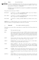
PIDsetpointcontrolrequiresfeedbackfromtheprocessinordertocomparetheprocessvariable“value”to
thesetpoint.Thedifferencebetweentheprocessvariable“value”andthesetpointiscalledtheerror.The
MICROSeriesControlwillincreaseordecreasethemotorspeedinanattempttominimizetheerror.By
constantlyadjustingthemotorspeed,thePIDcontrolwilldrivetheprocesstowardthesetpoint.Referto
thePIDblockdiagrambelow:
19.1 FEEDBACK DEVICES
AtransducerortransmitterisrequiredtomonitortheprocessvariableandprovidefeedbacktothePID
unit in order to compare the process variable feedback to the set point. A transducer outputs a signal
correspondingtoafixedrangeoftheprocessvariable.Atransmitterprovidesoffsetandgainadjustments
toallowtheoutputsignaltobeadjustedtocorrespondtodifferentrangesoftheprocessvariable.Typical
outputsignalsfortransducersandtransmittersare:0-5VDC,0-10VDC,or4-20mA.Thefeedbackdevice
mustbeexternallypowered,asthedrivedoesnothaveapowersupplyforsuchdevices.ProgramParameter
74-PIDFB(PIDFEEDBACKSOURCE)fortheappropriateterminal(TB-5AorTB-5B),andconnect
thefeedbackdeviceasdescribedbelow:
POT The positive signal wire (wiper) is connected to TB-5A, and the “high” lead is
connected to TB-6.
0-5, 0-10 VDC Connect the positive signal wire to TB-5A.
4-20 mA Connect the positive signal wire to TB-5B.
Thecommon,ornegativesignalwire,isconnectedtoTB-2(circuitcommon).
Feedbackdevicescan bedirectorreverseacting.Adirectactingdeviceoutputsasignalthatincreasesas
the process variable increases. A reverse acting device outputs a signal that decreases as the process variable
increases. The programming of Parameters 75 - FB @ MIN and 76 - FB @ MAX depend on the type of
feedbackdevicebeingused.
When using a direct acting transducer, Parameter 75 - FB @ MIN should be set to the value of the process
variablefeedbackcorrespondingtotheminimumfeedbacksignal(0VDCor4mA),andParameter76-FB
@MAXshouldbesettothevalueoftheprocessvariablefeedbackcorrespondingtothemaximumfeedback
signal(5or10VDC,or20mA).
Example 1: A 0-100 psi transducer outputs a 4 mA signal at 0 psi and 20 mA at 100 psi. Program Parameter
75 to 0.0 PSI, and Parameter 76 to 100.0 PSI (This assumes that Parameter 31 - UNITS is set to pid PSI,
andParameter33-UNITSDPissettoXXX.X).
77