
User guide


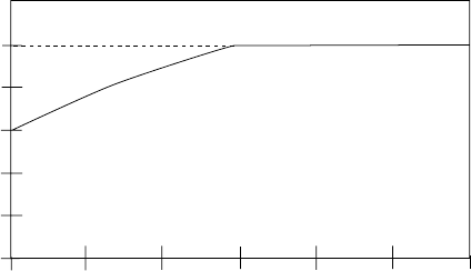
The“speed-compensated”thermaloverloadcircuitoffersadditionalprotectionfromhighloadconditions
atlowspeeds,wheremotorcoolingisoftenlesseffective(e.g.,motorswithshaft-mountedfans).Asseenon
thediagrambelow,thedrivereducestheallowablecontinuousoutputcurrentwhenoperatingatfrequencies
lessthan30Hz.
Example 2:A480Vac,20HPdriveisoperatingamotorat10Hz.Fromthediagram,adriveoperatingat
10Hzcandeliverabout75%ofitsoutputcurrentratingcontinuously.A480Vac,20HPdrive’soutput
current rating is 27 Amps. Therefore, the drive would be able to operate continuously at 20 Amps. The
drivewouldalsobeabletodeliver150%ofthatvalue(30Amps)foroneminutebeforetrippingintoan
OVERLOAD fault.
The“speedcompensated”thermaloverloadisthefactorydefaultandshouldbeusedinapplicationswhere
themotordoesnotnormallyexperiencehighloadsatlowspeedsforextendedperiodsoftime.
NOTE 1: The above diagram is based on a MOTOR OL setting of 100%. For lower MOTOR OL settings,
reducethe%CURRENTvaluesbythesamepercentage.Forexample,ifMOTOROLissetto75%,reduce
the % CURRENT values by 25%. Therefore, the curve shifts down, but the shape of the curve remains the
same.
The“non-compensated” thermal overloadcircuitallows 100% current continuously,and150% current
for one minute, at all speeds. In the example above, the motor operating at 10 Hz without
“speed-compensated”protectionwouldbeallowed tooperatecontinuouslyat27 Amps,andcoulddraw
40.5 Amps for one minute before tripping. Without sufficient motor cooling, this can result in motor
failure due to overheating.
The “non-compensated” circuit is selected by setting Parameter 22 - TORQUE to CT/NOCMP. The
“non-compensated”settingshouldonlybeusedinapplicationswherethemotorisproperlycooledatall
speeds, or the motor manufacturer has approved the motor for full-load operation at low speeds.
NOTE 2: The operation of the motor thermal overload circuit is affected by the setting of Parameter 34 -
LOAD MLT.
57
NON-COMPENSATED
SPEED COMPENSATED
100
80
60
40
20
10 20 30 40
50
60
FREQUENCY (Hz)
MAXIMUM CONTINUOUS
OUTPUT CURRENT (%)