
User guide


14 DYN BRAK (DYNAMICBRAKE)
This parameter enables the dynamic braking circuit. Set this parameter to ON only if the optional
dynamicbrakingcircuitboardandresistorsareinstalled.
Dynamicbraking isusedin applicationswherehigh-inertia loadsneedto bedeceleratedquickly. When
thisis attempted,themotorregeneratesvoltagebackinto thedrive, causingtheDCbusvoltage torise,
eventually resulting in a HI VOLTS fault. With the dynamic braking option, the DC bus voltage is
monitored,andwhenitreachesacertainlevel,atransistorisswitchedonthatconnectsanexternalresistor
bankacrosstheDCbus.Thisallowstheregeneratedenergyfromthemotortobedissipatedthroughthe
resistorsasheat,whichkeepstheDCbusvoltagebelowthetriplevel.
16 CURRENT (CURRENTLIMIT)
Thisparametersetsthemaximumallowableoutputcurrentofthedrive,whichalsodeterminesthetorque
capabilityofthemotor.Formostapplications,CURRENTisleftatthemaximumsetting,whichis150%
or180%(ofthedrive’soutputcurrentrating),dependingonwhethertheinputvoltagetothedriveislow
orhigh(seeParameter0-LINEVOLTS).RegardlessoftheCURRENTsetting,thedriveiscapableof
deliveringamaximumof150%currentforoneminute,and180%currentforapproximately30seconds,
beforetrippingintoanOVERLOADfault.SeeParameter17–MOTOROL.
The drive will enter current limit when the load demands more current than the drive can deliver, which
resultsinalossofsynchronizationbetweenthedriveandthemotor.Tocorrectthiscondition,thedrive
will enter FREQUENCY FOLDBACK, which commands the drive to decelerate in order to reduce the
output current andregainsynchronizationwiththemotor. When the overcurrent condition passes, the
drivewillreturntonormaloperationandacceleratebacktothespeedsetpoint.However,ifFREQUENCY
FOLDBACK cannot correct the condition and the drive remains in current limit for too long, it will trip
intoanOVERLOADfault.Ifthedriveenterscurrentlimitwhileaccelerating,thetimerequiredtoreach
thespeedsetpointwillbelongerthanthetimeprogrammedintoACCEL(Parameter8).
17 MOTOR OL (MOTOROVERLOAD)
The MICRO Series is UL approved for solid state motor overload protection. Therefore, a separate thermal
overloadrelay isnotrequired forsingle motorapplications.TheMOTOROVERLOAD circuitis used
to protect the motor from overheating due to excessive current draw. The trip time for the MOTOR
OVERLOAD setting is based on what is known as an “inverse I2t” function. This function allows the
drive to deliver 150% of the rated output current for one minute, and even higher current levels for shorter
periodsoftime.Oncetheoverloadcircuit“timesout”,thedrivewilltripintoanOVERLOADfault.
TheMOTOROVERLOADshouldbesettoavaluewhichisequaltotheratio(inpercentage)ofthemotor
full load current rating to the drive output current rating. This will result in an overload capacity of 150%
of the MOTOR current rating for one minute. If this parameter is set to 100%, the motor will be allowed
to draw 150% of the DRIVE output current rating for one minute. This distinction is important in cases
where the motor full load current rating is significantly less than the drive output current rating, such as
applicationswherethedriveisoversizedtomeettorquerequirements.
Example 1: A 5 Hp, 480 Vac drive is operating a 3 HP motor with a full load current rating of 4.8 amps.
Divide the motor current rating by the drive output current rating: 4.8 / 7.6 = 63%. Entering this value
will allow continuous operation at 4.8 amps, and will also allow the motor to draw 7.2 amps (150% of 4.8
amps)foroneminute.Ifthesettingisleftat100%,themotorcoulddraw11.4amps(150%of7.6amps)
for one minute before tripping the drive.
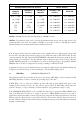
The MC Series drive has two options for thermal overload protection. One depends on the speed of the
drive,andtheotherdoesnot.Thediagrambelowillustratesthedifferencebetween“speedcompensated”
and“non-compensated”thermaloverloadprotection.
56