USER’S MANUAL Variable-frequency drives for 3-phase and single-phase AC motors 175318 175318PCM 175319 175319PCM 175320 175321PCM 175321 175321PCM 175310 175310PCM 175322 175322PCM 175323 175323PCM 175311 175311PCM
LIMITED WARRANTY A. Warranty - LEESON Electric warrants that its products will be free from defects in material and workmanship for a period of one (1) year from the date of shipment thereof. Within the warranty period, LEESON will repair or replace such products that are returned to LEESON or to the nearest Branch Office, with shipping charges prepaid. At our option, all return shipments are F.O.B. LEESON or its Branch Office.
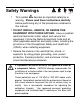
i Safety Warnings • This symbol denotes an important safety tip or SHOCK HAZARD AVOID HEAT KEE DR OID ATION warning. Please read these instructions carefully before performing any of the procedures contained in this manual. • DO NOT INSTALL, REMOVE, OR REWIRE THIS EQUIPMENT WITH POWER APPLIED. Have a qualified electrical technician install, adjust and service this equipment.
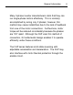
ii General Information The LEESON FHP Series are solid-state, variablefrequency AC motor drives. The FHP utilizes a 115 or 230 VAC, 50/60 Hz, single-phase input, and is factory calibrated for an output of 0 to 60 Hz. They will operate any 1 HP or smaller, 115 or 208/230-volt, three-phase-AC-induction, single-phase permanent split capacitor motor (see page v) and can be user calibrated for 0 through 120 Hz output.
General Information Many 3-phase inverter manufacturers claim that they can run single-phase motors effectively. This is normally accomplished by wiring only 2 phases; however, this method may cause instabilities due to the lack of feedback from one of the motor connections. Furthermore, motor torque will be reduced considerably because the phases are 120° apart. Although the FHP uses this method of connection, its fundamental design enables it to operate efficiently under these conditions.
iv General Information FHP SERIES FEATURES & BENEFITS • SOLID-STATE CIRCUITRY • SOLID-STATE REVERSING • ADJUSTABLE CARRIER FREQUENCY (4 kHz - 16 kHz) LED INDICATORS • MULTIPLE MOTOR OPERATION • THREE-PHASE AND SINGLE-PHASE MOTOR CONTROL POWER (green) FAULT (red) U V TORQUE (yellow) W TB501 TH501 L2 C501 TQ ADJUSTABLE CALIBRATION TRIMPOTS DECEL C502 ACCEL 115V MAX D BOOST L1 TB501 S3 S1 E1 E2 230V 1-2:VOLTAGE JMP502:INPUT TYPE 501:INPUT RANGE J501 TQ LIMIT optional ACCEPTS A 0
v Important Information Warning Caution should be taken when operating fan-cooled motors at low speeds because their fans may not move sufficient air to properly cool the motor. LEESON recommends “inverter-duty” motors when the speed range is beyond 10:1.
vi Contents Safety Warnings i General Information ii Important Information v Specifications 1 Dimensions 2 Installation 10 175324 Process Control Module (PCM) Mounting . . . . . . . . . . . . . . . . . . . . . .10 Mounting . . . . . . . . . . . . . . . . . . . . . . . . . . . . . . . . . . . . . . . . . . . . . . . . . . . . . .15 Wiring . . . . . . . . . . . . . . . . . . . . . . . . . . . . . . . . . . . . . . . . . . . . . . . . . . . . . . . . .17 Shielding guidelines . . . . . . . . . . . .
Contents vii Calibration 44 Calibration Procedure Setup for 60 Hz Motors: . . . . . . . . . . . . . . . . . . . . . . . .46 MAXIMUM SPEED (MAX SPD) . . . . . . . . . . . . . . . . . . . . . . . . . . . . . . . . . .46 TORQUE LIMIT (TQ LIMIT) . . . . . . . . . . . . . . . . . . . . . . . . . . . . . . . . . . . . .47 ACCELERATION (ACCEL) . . . . . . . . . . . . . . . . . . . . . . . . . . . . . . . . . . . . .48 DECELERATION (DECEL) . . . . . . . . . . . . . . . . . . . . . . . . . . . . . . . . . . . . .
viii Illustrations Figure Figure Figure Figure Figure Figure Figure Figure Figure Figure Figure Figure Figure Figure Figure Figure Figure Figure Figure Figure Figure Figure Figure Figure Figure Figure Figure Figure Figure Figure 1. FHP Series Features & Benefits . . . . . . . . . . . . . . . . . . . . . . . . . . . . . . . . . . . . . . . . . .iv 2. 175318, 175320, & 175321 Dimensions . . . . . . . . . . . . . . . . . . . . . . . . . . . . . . . . . . . .2 3. 175322 and 175323 Dimensions . . . . . . . . .
1 Specifications Drive 175318 175319 175320 175321 175310 175322 175323 1-Phase Input (VAC) 230 *115 / 230 115 230 *115 / 230 115 230 1 or 3-Phase Output (VAC) 230 230 115 230 230 115 230 Max HP ¼ ¼ ¼ ½ ½ ½ 1 Max Continuous Output Current (AC) 1.2 1.2 2.4 2.4 2.4 4.0† 4.0† 175311 *115 / 230 230 1 4.0† * AC Amps In 3 7/3 7 7 10 / 7 10 10 15 / 10 Connect only 115 VAC line input to the 115 VAC terminals.
H 0.96 [24] 2.12 [54] JMP501 IC502 POWER FAULT TQ LIMIT BOOST W AC AC 2.48 [ 63.0] 2.68 [68.1] 2.03 [51.6] TOTAL HEIGHT (H) (TOP OF CAP TO BOTTOM OF CHASSIS) TQ Figure 2. 175318, 175320, & 175321 Dimensions 175318 175320 175321 C510 J501 ACCEL DECEL V - L1 L2 J503 ALL DIMENSIONS IN INCHES [MILLIMETERS] E2 E1 S1 S2 S3 D 0.97 [25] 2.72 [69] 3.70 [94] TB501 U 3.80 [97] 4.
E2 E1 S1 S2 S3 D 3.68 [93.5] DECEL POWER 6.90 [175] 6.30 [160] IC502 T FAULT BOOST Y W AC AC - L1 L2 J502 Figure 3. 175322 and 175323 Dimensions ALL DIMENSIONS IN INCHES [MILLIMETERS] C510 U J503 0.13 [3] 1.00 [25] 0.7 [18] 3.00 [72] 4.
4 Dimensions 4.30 [109] 3.80 [97] U V W TB501 TQ 3.70 [94] TQ LIMIT J503 FAULT 1-2:VOLTAGE 2-3:CURRENT JMP502:INPUT TYPE JMP501:INPUT RANGE 1:0-5VDC 2:0-10VDC 3:4-20MA AC AC 2.72 [69] - L2 J502 D S2 S1 E1 1 2 3 TB501 0.97 [25] L1 H E2 E1 S1 S2 S3 D 2.12 [54] 0.96 [24] TOTAL HEIGHT (H) (TOP OF CAP TO BOTTOM OF CHASSIS) 175318PCM 2.03 [51.6] 175320PCM 2.68 [68.1] 175321PCM 2.48 [63.0] ALL DIMENSIONS IN INCHES [MILLIMETERS] Figure 4.
Dimensions U Y W 4.40 [112] TB501 DECEL 3.00 [72] J503 FAULT 1-2:VOLTAGE JMP502:INPUT TYPE 2-3:CURRENT 3:4-20MA 1:0-5VDC JMP501:INPUT RANGE POWER AC AC - L2 J502 D S3 S2 TB501 1 2 3 E2 E1 L1 0.70 [18] 6.30 [160] 6.90 [175] ALL DIMENSIONS IN INCHES [MILLIMETERS] E2 E1 S1 S2 S3 D 3.68 [93.5] 1.00 [25] 0.12 [3] Figure 5.
2.12 [54] 0.96 [24] H ALL DIMENSIONS IN INCHES [MILLIMETERS] E2 E1 S1 S2 S3 D JMP501 ACCEL DECEL TQ IC502 TQ V C502 TH501 C501 3.02 [76.7] Figure 6. 175319 & 175310 Dimensions 2.56 [65.0] 175310 TOTAL HEIGHT (TOP OF CAP TO BOTTOM OF CHASSIS) C510 J501 U 175319 0.97 [25] 2.72 [69] 3.70 [94] TB501 3.80 [97] 4.
0.13 [3] 1.00 [25] E2 E1 S1 S2 S3 D 4.45 [113] C510 U C502 TH501 6.90 [175] 6.30 [160] IC502 TQ Y C501 W J501 L2 230V L1 Figure 7. 175311 Dimensions ALL DIMENSIONS IN INCHES [MILLIMETERS] TB501 0.70 [18] 3.00 [72] 4.
Dimensions 4.30 [109] 3.80 [97] U V W TB501 TH501 L2 DECEL TQ ACCEL C501 3.70 [94] 2.72 [69] 1-2:VOLTAGE JMP502 JMP502:INPUT TYPE 115V J501 2-3:CURRENT 1:0-5VDC 2:0-10VDC 3:4-20MA JMP501:INPUT RANGE C502 D S3 0.97 [25] L1 2 3 TB501 S2 S1 E1 E2 230V 8 H E2 E1 S1 S2 S3 D 2.00 [51] 0.96 [24] TOTAL HEIGHT (TOP OF CAP TO BOTTOM OF CHASSIS) 175319PCM 2.56 [65.0] 175310PCM 3.02 [76.7] ALL DIMENSIONS IN INCHES [MILLIMETERS] Figure 8.
Dimensions 6.30 [160] U Y W TH501 L2 TQ 3.00 [76] C501 C502 230V 1-2:VOLTAGE 2-3:CURRENT JMP502:INPUT TYPE J501 L1 1 2 3 0.70 [18] 6.90 [175] ALL DIMENSIONS IN INCHES [MILLIMETERS] E2 E1 S1 S2 S3 D 4.45 [113] Figure 9.
10 Installation 175324 Process Control Module (PCM) Mounting The FHP Series PCM Adder Board accepts a 0 - 5 VDC, 0 - 10 VDC, or 4-20 mA signal and outputs an isolated 0-5 VDC signal without requiring additional panel space. It mounts directly over the main AC board (bottom board) thus maintaining the same footprint. Step-by-step information for mounting the PCM Adder Board to a FHP Series drive is shown on pages 12 - 14.
Installation 11 MAIN AC BOARD U (BOTTOM BOARD) Y W TB501 TH501 L2 C501 PCM ADDER BOARD C502 D 230V 1-2:VOLTAGE 2-3:CURRENT JMP502:INPUT TYPE J501 L1 PARTS SUPPLIED IN THIS KIT J501 PCM ADDER BOARD (1) JUMPER (1) 1-2:VOLTAGE JMP502:INPUT TYPE 2-3:CURRENT 1:0-5VDC 2:0-10VDC 3:4-20M D S3 TB501 S2 S1 E1 6-PIN HEADER (1) PCB STANDOFF (2) SHOULDER WASHER (1) 0.578" NYLON SPACER (1) 6-32 x 1 5/16" PHILLIPS SCREW (1) Required Tools: Phillips Screwdriver Figure 10.
Installation U V W TB501 H501 L2 C501 C502 115V J501 230V C510 L1 STEP #1 USING A PHILLIPS SCREWDRIVER REMOVE SCREW AND PLASTIC CAP FROM BOTTOM BOARD AND DISCARD. NOTE: DO NOT REMOVE THE SHOULDER WASHER FROM THE BOTTOM BOARD. U V W TB501 TH501 L2 DECEL C501 TQ STEP #2 C502 J501 115V PLACE THE JUMPER (NOTCH SIDE UP) ON JMP501 OF THE BOTTOM BOARD.
Installation U V W T TH501 L2 C501 TQ C502 STEP #3 115V J501 2 INSTALL TWO (2) PLASTIC STANDOFFS ONTO BOTTOM BOARD 230V C510 L1 U V W TB501 TH501 L2 C501 TQ STEP #4 JMP501 C502 115V J501 J501 IC502 230V C510 L1 SNAP THE SHORT SIDE OF THE 6-PIN HEADER INTO J501 LOCATED ON THE BOTTOM BOARD J501 J501 VIEW EW 1-2:VOLTAGE JMP502:INPUT TYPE 2:0-10VDC 3:4-20MA 1-2:VOLTAGE JMP502:INPUT TYPE STEP #5 INSERT THE SHOULDER WASHER (included with the kit) THROUGH THE TOP SIDE OF
14 Installation J501 1-2:VOLTAGE 2-3:CURRENT JMP502:INPUT TYPE 2:0-10V 1:0-5VD 3:4-20M JMP501:INPUT RA U V W D L2 TB501 TH501 DECEL C501 STEP #7 J501 JMP501 POSITION THE PCM ADDER BOARD OVER THE BOTTOM BOARD AS SHOWN. C502 115V J501 IC502 230V C510 L1 NOTE: First align the bottom holes of J501 (on the PCM adder board) with the 6 pin header installed on the bottom board. The PCM adder board will snap into place at J501 and the two standoffs.
Installation 15 Mounting Warning DO NOT install, rewire, or remove this control with input power applied. Doing so may cause fire or serious injury. Make sure that you read and understand the Safety Warnings before attempting installation. NOTE: Horizontal mouting may require derating the drive. See your LEESON representative for more information • It is recommended that the drive be oriented with the chassis vertical for best heat dissipation.
16 Installation • Protect the drive from dirt, moisture, and accidental contact. Provide sufficient room for access to the terminal block and calibration trimpots. • Mount the drive away from heat sources. Operate the drive within the specified ambient operating temperature range. • Prevent loose connections by avoiding excessive vibration of the drive. • The chassis must be earth grounded.
Installation Wiring Warning 쇵 DO NOT install, rewire, or remove this control with input power applied. Failure to heed this warning may result in fire, explosion, or serious injury. Circuit potentials are at 115 or 230 VAC above ground. To prevent the risk of injury or fatality, avoid direct contact with the printed circuit board or with circuit elements. Do not disconnect any of the motor leads from the drive unless power is removed. Opening any one motor lead may destroy the drive.
18 Installation Shielding guidelines Warning Under no circumstances should power and logic leads be bundled together. Induced voltage can cause unpredictable behavior in any electronic device, including motor controls. As a general rule, LEESON recommends shielding of all conductors. If it is not practical to shield power conductors, LEESON recommends shielding all logic-level leads.
Installation 19 If the drive continues to pick up noise after grounding the shield, it may be necessary to add AC line filtering devices, or to mount the drive in a less noisy environment. Logic wires from other input devices, such as motion controllers and PLL velocity controllers, must be separated from power lines in the same manner as the logic I/O on this drive. Heat sinking LEESON 1-HP FHP drives (175322, 175323, & 175311) drives are delivered with a factory-installed heat sink.
20 Installation Fusing FHP series drives require external AC power line fuses. Connect the external line fuse(s) in series with the AC voltage input. See Connections on page 22. Use fastacting fuses rated for 250 VAC or higher. See Table 1 for recommended line fuse sizes. Table 1.
Installation 21 Speed adjust potentiometer Warning Be sure that the potentiometer tabs do not make contact with the potentiometer enclosure. Grounding the input will cause damage to the drive. Mount the speed adjust potentiometer through a 0.38 in. (10 mm) hole with the hardware provided (Figure 11). Install the circular insulating disk between the panel and the 10K ohm speed adjust potentiometer. Twist the speed adjust potentiometer wire to avoid picking up unwanted electrical noise.
22 Installation Connections Warning DO NOT connect this equipment with power applied. Failure to heed this directive may result in fire or serious injury. LEESON strongly recommends the installation of a master power switch in the voltage input line. The switch contacts should be rated at a minimum of 200% of motor nameplate current and 250 volts.
Installation V 23 W LIMIT J503 AULT OWER AC AC - * FUSE START/STOP SWITCH L2 J502 FUSE 115 / 230 VAC LINE INPUT L1 * Do not add fuse to L2 unless line voltage is 230 VAC. Figure 12.
24 Installation Doubler FHP Series Drives (175319, 175310, 175311) Warning Ꮨ Do not connect 230 VAC line input when the drive is set for 115 VAC input. This will result in severe damage to the motor and drive, and can lead to explosion and/or injury. Check jumper settings before connecting AC power input. Connect AC power input to L1 and L2 as shown in Figure 13 and 14 (pages 25 & 26), depending on your power needs.
Installation 25 WARNING V Ꮨ W TH501 L2 DECEL TQ ACCEL C501 TQ Do not connect 230 VAC line input when the drive is set for 115 VAC input. This will result in severe damage to the motor and drive, and can lead to explosion and/or injury. C502 START/STOP SWITCH 115V J501 115 VAC LINE INPUT 230V IC502 L1 FUSE J501 Voltage Doubler Mode Setting (115 VAC in - 230 VAC out) Figure 13.
26 Installation V W TH501 L2 ECEL TQ CCEL C501 TQ C502 115V J501 FUSE START/STOP SWITCH 230 VAC LINE INPUT 230V IC502 L1 FUSE J501 No Voltage Doubler (230 VAC in - 230 VAC out) Figure 14.
Installation 27 Motor connections (all FHP-series controls) Single-phase operation For single-phase operation, connect the motor as shown in Figure 15 (page 28). Ensure that the prewired capacitor and its associated motor coil are connected to terminals U and V as shown. This connection may be internal if using a 2-wire motor. If the motor has three leads, you must make this connection yourself. To reverse a single phase split capacitor motor, connect the motor as shown in Figure 16 (page 29).
28 Installation MOTOR WINDINGS NOTE PREWIRED RUN CAPACITOR This connection may be internal to the motor (2 wire leads). If not, you must make this connection yourself. DO NOT use a DIRECTION switch with this set-up. See Figure 16 on Page 29 for setup using a DIRECTION switch. U V W TB501 BOOST DECEL TQ ACCEL TQ LIMIT J503 FAULT J501 JMP501 POWER AC AC - IC502 C510 L2 J502 L1 Figure 15.
Installation MOTOR WINDINGS NOTE Motor starter cap must be removed from the circuit. This method works with most (but not all) motors. AUXILLIARY WINDING WITHOUT CAPACITOR U V W TB501 DECEL TQ ACCEL TQ LIMIT J503 FAULT MAX J501 JMP501 POWER AC AC - IC502 C510 L2 J502 L1 Figure 16.
30 Installation MOTOR WINDINGS U V W TB501 DECEL TQ ACCEL TQ LIMIT J503 FAULT MAX J501 JMP501 POWER AC AC - IC502 C510 L2 J502 L1 Figure 17.
Installation 31 Speed Adjust Potentiometer Connections Connect a speed adjust potentiometer to terminals S1, S2 and S3. Make sure the potentiometer is connected so that the motor speed will increase as the wiper (S2) is turned clockwise (CW). See Figure 18 below. TB501 E2 10K OHM SPEED ADJUST POTENTIOMETER E1 S1 U V W TB501 01 DECEL TQ S2 ACCEL LIMIT S3 FAULT J501 CW JMP501 D POWER AC IC502 C510 Figure 18.
32 Installation Voltage Follower Connections Instead of using a speed adjust potentiometer, the drive may be wired to follow a 0 - 5 VDC isolated voltage signal (Figure 19). Connect the signal input (+) to S2 and signal common (-) to S1. Make no connection to S3. A potentiometer can be used to scale the analog input voltage. The FHP-PCM adder board may be used to scale and isolate an analog input voltage (see Page 35).
Installation 33 Signal and Optional Switch Connections All signal and switch connections are made at TB501. Terminal block orientation and terminal names are identical for all FHP series drives. Use 20 - 24 AWG wire for speed adjust potentiometer and switch connections. ENABLE/DISABLE switch Connect a single-pole, single-throw ENABLE/DISABLE switch between the ENABLE (E2) and COMMON (E1) terminals as shown. Open the switch to disable the drive and coast to a stop.
34 Installation DIRECTION (D) switch Connect a single-pole, single-throw DIRECTION switch between the (D) and COMMON (E1) terminals as shown in Figure 21 below. Opening the switch will cause the motor to rotate in the forward direction; closing the switch will reverse motor rotation. The drive will decelerate the motor to a stop, (at the DECEL trimpot setting), before reversing, so there is no need to wait for the motor to coast to a stop before changing direction.
Installation 35 Voltage or Current Follower (PCM models) PCM series drives can be configured to follow a grounded (non-isolated) voltage or current signal. To configure the drive to follow a voltage or current signal, connect the signal leads to the S1 and S2 terminals on TB501. Ensure that the following jumper terminals are properly set: JMP501 Input Range Settings Set jumper in position 1 for 0 - 5 VDC signal input. Set jumper in position 2 for 0 - 10 VDC signal input.
E1 S2 S3 DIRECTION TO SPEED POT or SIGNAL INPUT S1 D PCM ADDER BOARD TB501 JMP501:INPUT RANGE 1 2 3 Figure 22.
37 Operation Warning 쇵 Dangerous voltages exist on the drive when it is powered, and up to 60 seconds after power is removed and the motor stops. BE ALERT. High voltages can cause serious or fatal injury. Do not change jumper settings with power applied. Ensure that jumper settings are compatible with the motor being controlled. Voltage Input Warning for Doubler Drives 쇵 DO NOT connect 230 VAC line input when the drive is set for 115 VAC input.
38 Operation Voltage Doubler Warning DO NOT connect 230 VAC line input when drive is set for 115 VAC input. This will result in severe damage to the motor and drive, and possible explosion or severe injury. Doubler drives are equipped with a unique voltage-doubling feature, for use when 230 VAC input voltage is not available. This feature converts a 115 VAC input to a 230 VAC output, for use with 230V motors. The drive output current rating remains the same.
Operation 39 Startup Warning DO NOT change jumper settings with power applied. Ensure that jumper settings are compatible with the motor being controlled. Before applying power, verify that no conductive material is present on the printed circuit board. 1. Verify that no conductive material is present on the PCB. 2. Verify that the correct voltage is connected to the inputs before applying power. DO NOT CONNECT 230 VAC line voltage to a 115 VAC drive.
40 Operation 7. If you attempt to startup and the yellow TQ LED comes on, the control has entered torque limit mode. To avoid this occurrence, you may: a. increase the torque limit setting*, or b. lengthen the acceleration time enough to accomodate the needed starting torque by adjusting the ACCEL trimpot. * Do not set the torque limit setting above 150% of the motor’s nameplate current rating.
Operation 41 Starting and stopping methods To coast the motor to a stop Open the ENABLE/DISABLE switch, or remove the jumper between the ENABLE (E2) and COMMON (E1) terminals of TB501. Refer to the Application Notes section (page 51) for instructions on switch installation. Thermal protection of the motor The enable input can also act as a motor thermal protection circuit for motors having a built-in thermal protector.
42 Operation ENABLE / DISABLE SWITCH CLOSE TO ENABLE THERMAL OVERLOAD SWITCH TB501 E2 (ENABLE) E1 (COMMON) S1 S2 S3 D Figure 23.
Operation 43 Line starting and line stopping Warning LEESON strongly recommends the installation of a master power switch in the voltage input line (see Power and Fuse connections, page 22). The switch contacts should be rated at a minimum of 200% of motor nameplate current and 250 volts. Line starting and line stopping (applying and removing AC voltage input) is not recommended and should be used for emergency stopping only.
44 Calibration Warning Dangerous voltages exist on the drive when it is powered, and up to 60 seconds after power is removed and the motor stops. When possible, disconnect the voltage input from the drive before adjusting the trimpots. If the trimpots must be adjusted with power applied, use insulated tools and the appropriate personal protection equipment. BE ALERT. High voltages can cause serious or fatal injury. The FHP series has five user-adjustable trimpots.
1:0-5VDC on isolation board ZERO SET MAX ACCEL TB501 ACCEL DECEL TQ TQ C502 TH501 C501 W J501 L1 JMP502:INPUT TYPE 2-3:CURRENT 1-2:VOLTAGE TB501 S3 D S2 JMP501:INPUT RANGE 2:0-10VDC S1 3:4-20MA E1 2 3 Figure 24.
46 Calibration Calibration Procedure Setup for 60 Hz Motors: 1. Set the ENABLE switch to the DISABLE (open) position. If no switch is installed, remove the jumper between the (E2) and (E1) terminals of TB501. 2. Set the DIRECTION switch to the FWD (open) position. If no switch is installed, remove the jumper between the (D) and (E1) terminals of TB501. 3. Set all trimpots except TQ LIMIT and MAX fully counterclockwise (CCW). 4. Set the TQ LIMIT trimpot to maximum (full CW). 5.
Calibration 47 TORQUE LIMIT (TQ LIMIT) Warning Although the TQ LIMIT trimpot can be set up to 150% of the drive nameplate rating, continuous operation beyond the drive nameplate rating may cause damage to the motor and/or drive. 1. With no power applied to the drive, connect a (true RMS) ammeter in series with one of the motor leads. 2. Set the TQ LIMIT trimpot to full CCW. 3. Carefully lock the motor shaft. Ensure that the motor is firmly mounted. 4. Apply line power. The motor should be stopped. 5.
48 Calibration ACCELERATION (ACCEL) 1. Set the speed adjust potentiometer to zero (full CCW) and wait for the motor to come to a stop (or minimum speed). 2. Set the speed adjust potentiometer or reference signal to maximum speed (full CW) and note the time the motor takes to accelerate to maximum speed. 3. If the acceleration time differs from the desired time, adjust the ACCEL trimpot until the desired time is reached. Rotating the ACCEL trimpot CW increases the acceleration time.
Calibration 49 BOOST The boost trimpot is used to increase motor torque at low speeds. The minimum setting is sufficient for most applications and does not need to be adjusted. If the motor stalls or runs erratically at very low speeds (below 10 Hz), the boost trimpot may need adjustment. 1. Run the motor at the lowest continuous frequency/speed required. 2.
50 Calibration Calibration Procedure Conclusion 1. Set the speed adjust potentiometer to zero (full CCW). 2. Disable the drive by opening the ENABLE/DISABLE switch or removing the jumper from TB501 (E2) and (E1) terminals. 3. Remove power to the motor and drive. Calibration is now complete.
51 Application Notes Independent adjustable speeds with DIR switch Replace the speed adjust potentiometer with two singlepole multi-position switches, and two or more potentiometers in parallel, with a total parallel resistance of 10K ohms. Figure 25 shows the connection of two independent speed adjust potentiometers that can be mounted at two separate operating stations. TB501 E2 FORWARD SPEED 20K OHM E1 REVERSE SPEED S1 20K OHM S2 S3 FORWARD D (DIRECTION) REVERSE Figure 25.
52 Application Notes RUN/JOG switch Using a RUN/JOG switch is recommended in applications where quick stopping is not needed and frequent jogging is required. Use a single-pole, two-position switch for the RUN/JOG switch, and a single-pole, normally open, momentary operated pushbutton for the JOG pushbutton. Connect the RUN/JOG switch and JOG pushbutton to terminal board TB501 as shown in Figure 26. The motor coasts to a stop when the RUN/JOG switch is set to JOG.
Application Notes 53 Single speed potentiometer control of multiple motors Warning The combined current draw of all motors must not exceed the current rating of the drive. The FHP series of controls is capable of operating up to eight 3-phase motors simultaneously. All motors must be of the same type and must control similar loads. Connect each motor as shown in Figure 27 below. MOTOR A U CW V MOTOR B W S3 S2 S1 10K OHM SPEED ADJUST POTENTIOMETER VFD SERIES DRIVE Figure 27.
54 Application Notes Quick Reversing To reverse the direction of motor shaft rotation, install a DPDT center off switch as shown below (Figure 28). The drive will brake the motor before reversing, so there is no need to wait for the motor to coast to a stop before changing direction. TB501 E2 (ENABLE) DPDT CENTER OFF SWITCH E1 (COMMON) FWD S1 STOP REV S2 S3 D Figure 28.
55 Troubleshooting Warning Dangerous voltages exist on the drive when it is powered, and up to 60 seconds after power is removed and the motor stops. When possible, disconnect the voltage input from the drive while troubleshooting. BE ALERT. High voltages can cause serious or fatal injury. Before troubleshooting Perform the following steps before starting any procedure in this section: • Disconnect AC voltage input from the drive. Wait 60 seconds for power to discharge.
56 Troubleshooting • Verify that there are no short circuits or grounded connections. • Check that the drive’s rated phase current and RMS voltage are consistent with the motor ratings.
Troubleshooting Diagnostic LEDs LEESON FHP Series drives are equipped with diagnostic LED’s to assist the user in troubleshooting and monitoring equipment status while in use. Refer to Figure 29 (page 58) for diagnostic LED locations. POWER LED The green POWER LED is on when AC line voltage is applied and the control’s low-voltage power supply is operational. FAULT LED The red FAULT LED turns on when the drive output is locked out or not ENABLED and any one of the following fault conditions occur: 1.
58 Troubleshooting TQ LIMIT LED The yellow TQ LIMIT LED is on when the drive output current exceeds the threshold set by the TQ LIMIT trimpot. When the TQ LIMIT LED turns on, shut down the motor and drive by disabling or removing power. Check the motor to make sure it is not jammed or overloaded. The TQ LIMIT trimpot may need to be recalibrated. See the Calibration section (page 47) for information on calibrating the TQ LIMIT trimpot.
Troubleshooting Problem External line fuse blows External line fuse does not blow, but the motor does not run 59 Possible Cause Suggested Solution 1. Line fuses are the wrong size. 1. Check that line fuses are properly sized for the motor being used. 2. Motor or motor cable is shorted to ground. 2. Check motor cable and motor for shorts. 3. Nuisance tripping caused by a combination of ambient conditions and high-current spikes (i.e. reversing). 3.
60 Troubleshooting Problem External line fuse does not blow, but the motor does not run (cont.) Motor runs too slow or too fast at set speed Possible Cause Suggested Solution 3. Drive is “tripped” off or has gone into thermal overload. 3. Disable, then reenable the drive. 4. Drive has been disabled. 4. Ensure that ENABLE (EN) and COM terminals are properly connected. 5. Drive is in current limit. 5. Verify that motor is not jammed. Increase TQLIM setting if it is set too low (page 47). 6.
Troubleshooting Problem Motor will not reach the desired speed Possible Cause 61 Suggested Solution 1. MAX SPD setting is too low. 1. Increase MAX SPD setting (page 46). 2. Nominal input voltage may be too low for motor 2. Compare motor voltage to input voltage; replace motor if necessary 3. Motor is overloaded. 3. Check motor load. Resize the motor or drive if necessary. Motor pulsates or surges under load 1. Motor “bouncing” in and out of torque limit. 1.
62 Troubleshooting Problem TQ is unsatisfactory at high speeds. Possible Cause Suggested Solution 1. TQ LIMIT set too low. 1. Check TQ LIM setting (page 41). 2. Load may exceed rating of motor/drive. 2. “Fix” load (i.e., straighten mounting, coupling, etc.); or replace motor and drive with motor and drive rated for higher horsepower. 3. Nominal input voltage may be too low for motor. 3. Compare motor voltage to input voltage. Replace motor if necessary.
Troubleshooting 63 Optional C510 Capacitor Kit (p/n: 175325) In some applications, lowering carrier frequency reduces switching losses and increases bearing life in some motors. LEESON provides an optional capacitor kit for lowering the carrier frequency. The default carrier frequency on FHP controls is 16kHz. Using one of the capacitors supplied in the kit, the carrier frequency can be lowered to a range of 12kHz to 4kHz. Note: Audible noise will increase when the carrier frequency is lowered.
64 Troubleshooting U V TB501 BOOST DECEL TQ ACCEL TQ LIMIT Cap Label 3n3 J100 FAULT POWER IC502 C510 CARRIER FREQUENCY CAPACITOR (C510) Insert the 2-pins of the carrier frequency capacitor into the 2 socket-holes (C510) located on bottom board. Figure 30.
Troubleshooting 65 Replacement Parts Replacement parts are available from LEESON Electric and its distributors for this drive series. Table 2. Replacement Parts Potentiometer Kit 10K ohm, 5W Potentiometer 175325 Capacitor Kit 12 kHZ Capacitor 10 kHz Capacitor 8 kHz Capacitor 4 kHz Capacitor 175324 PCM Kit PCM Adder Board (1) PCB Standoffs (2) Jumper (1) 6-Pin Header (1) Shoulder Washer (1) 0.
DISCLAIMER The information and technical data in this manual are subject to change without notice. LEESON Electric makes no warranty of any kind with regard to this material, including, but not limited to, the implied warranties of merchantability and fitness for a particular purpose. LEESON Electric assumes no responsibility for any errors that may appear in this manual and makes no commitment to update or to keep current the information in this manual. 2100 Washington Street Grafton, WI 53024-0241, U.S.