
User guide
9Installation
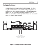
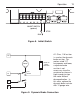
L1 L2 A1 A2 S3 S2
0 - 5 VDC
ISOLATED VOLTAGE
SIGNAL INPUT
+-
S1
H2
H1
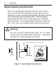
Figure 6. Voltage Follower Connections
Voltage follower
Instead of using a speed adjust potentiometer, the drive
may be wired to follow a 0 - 5 VDC voltage signal that is
isolated from earth ground (Figure 6). Connect the signal
input (+) to S2. Connect the signal common (-) to S1.
Make no connection to S3. A potentiometer can be used to
scale the analog input voltage.