ELECTRIC MOTORS, GEARMOTORS AND DRIVES Variable Speed AC Motor Drives SM-Basic Installation and Operation Manual
EC Declaration of Conformity In accordance with EN45014:1998 We, Leeson Electric Corporation 2100 Washington Street Grafton, Wisconsin 53024 USA declare under sole responsibility that the following equipment to which this declaration relates, meets the essential health and safety requirements and is in conformity with the relevant sections of the applicable EC standards and other normative documents.
Manual Number: IMSN01 TABLE OF CONTENTS 1.0 GENERAL..................................................................................... 1 2.0 SM-Basic DIMENSIONS................................................... 2 3.0 SM-Basic MODEL DESIGNATION CODE.................... 3 4.0 SM-Basic SPECIFICATIONS............................................ 3 5.0 SM-Basic RATINGS............................................................ 4 6.0 INSTALLATION.....................................................
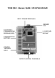
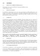
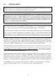
THE SM-Basic SUB-MICRO DRIVE INPUT POWER TERMINALS GROUND LUG ELECTRONIC PROGRAMMING MODULE (EPM) 2-DIGIT LED DISPLAY PROGRAMMING BUTTONS CONTROL TERMINAL STRIP OUTPUT (MOTOR) TERMINALS
1.0 GENERAL 1.1 PRODUCTS COVERED IN THIS MANUAL This manual covers the Leeson Electric Corporation SM-Basic Series Variable Frequency Drive. 1.2 PRODUCT CHANGES Leeson Electric Corporation reserves the right to discontinue or make modifications to the design of its products without prior notice, and holds no obligation to make modifications to products sold previously. Leeson Electric Corporation also holds no liability for losses of any kind which may result from this action. 1.
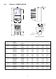
2.0 SM-Basic DIMENSIONS 0.38" R H W 0.38" 0.18" 0.69" D P 0.19" Dia. Slot Mounting Tab Detail INPUT VOLTAGE MODEL H W D P R 0.25 120/208/240 208/240 174374 174378 5.75 5.75 2.88 2.88 3.76 3.76 0.80 0.80 4.37 4.37 0.5 120/208/240 208/240 400/240 174375 174379 174384 5.75 5.75 5.75 2.88 2.88 2.88 3.76 3.76 3.76 0.80 0.80 0.80 4.37 4.37 4.37 1 120/208/240 400/480 480/590 174376 174380 174385 5.75 5.75 5.75 3.76 2.88 2.88 5.24 4.56 4.56 1.90 1.60 1.60 4.37 4.37 4.37 1.
3.0 SM-Basic MODEL DESIGNATION CODE 4.
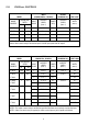
5.0 SM-Basic RATINGS MODEL MODEL NUMBER FOR MOTORS RATED HP 174374 0.25 kW 0.20 INPUT (120/208/240 Vac, 50-60 Hz) OUTPUT (0-200/230 Vac) CURRENT (AMPS) CURRENT (AMPS) WATTS (NOTE 1) (NOTE 3) 1.4/1.6/1.4 21 INPUT PHASE 1 (NOTE 1) POWER (kVA) 6.0/3.5/3.0 0.72 HEAT LOSS 174375 0.5 0.37 1 9.2/5.3/4.6 1.1 2.2/2.5/2.2 28 174376 1.0 0.75 1 15.8/9.1/7.9 1.9 4.0/4.6/4.0 46 174377 1.5 1.1 1 21.3/12.3/10.7 2.6 5.4/6.2/5.
6.0 INSTALLATION NOTE! SM-Basic drives are intended for inclusion within other equipment, by professional electrical installers. They are not intended for stand-alone operation. WARNING! DRIVES MUST NOT BE INSTALLED WHERE SUBJECTED TO ADVERSE ENVIRONMENTAL CONDITIONS SUCH AS: COMBUSTIBLE, OILY, OR HAZARDOUS VAPORS OR DUST; EXCESSIVE MOISTURE OR DIRT; VIBRATION; EXCESSIVE AMBIENT TEMPERATURES. CONSULT AC TECHNOLOGY FOR MORE INFORMATION ON THE SUITABILITY OF A DRIVE TO A PARTICULAR ENVIRONMENT.
6.1 INSTALLATION AFTER A LONG PERIOD OF STORAGE WARNING! Severe damage to the drive can result if it is operated after a long period of storage or inactivity without reforming the DC bus capacitors! If input power has not been applied to the drive for a period of time exceeding three years (due to storage, etc), the electrolytic DC bus capacitors within the drive can change internally, resulting in excessive leakage current.
7.0 INPUT AC POWER REQUIREMENTS WARNING! Hazard of electrical shock! Capacitors retain charge after power is removed. Disconnect incoming power and wait until the voltage between terminals B+ and B- is 0 VDC before servicing the drive. The input voltage must match the nameplate voltage rating of the drive. Voltage fluctuation must not vary by greater than 10% overvoltage or 15% undervoltage.
Minimum voltage rating of the protection device should be 250 Vac for 120/208/240 Vac and 208/ 240 Vac rated drives. UL Class CC fast-acting, current limiting type fuses should be used when input fusing is required. Select fuses with low I 2 T values, rated at 200,000 AIC. Recommended fuses are Bussman KTK-R. Similar fuses with equivalent ratings by other manufacturers may also be acceptable. 8.0 POWER WIRING WARNING! Hazard of electrical shock! Capacitors retain charge after power is removed.
9.0 SM-Basic POWER WIRING DIAGRAM THREE PHASE INPUT (where applicable) L1 L2 120 Vac SINGLE PHASE INPUT (where applicable) L1 L3 208/240 Vac SINGLE PHASE INPUT (where applicable) L2 N OUTPUT (ALL) T1 T2 T3 B- B+ L1 L2 L3* + 3 PHASE AC MOTOR DC BUS VOLTAGE WARNING! Do not connect incoming AC power to output terminals T1, T2, or T3. Severe damage to the drive will result. NOTES: 1. WIRE AND GROUND IN ACCORDANCE WITH NEC OR CEC, AND ALL APPLICABLE LOCAL CODES. 2.
10.0 CONTROL WIRING WARNING! Hazard of electrical shock! The SM-Basic control terminals are not isolated from line voltage! Line voltage is present between the control terminals and ground. Do not touch! Disconnect input power and wait three minutes before making connections to the control terminals.
10.5 SPEED REFERENCE SELECTION If a speed pot is to be used to control the drive speed, terminal TB-13A, 13B, or 13C (Parameter 10, 11, or 12) may be programmed as the input select for the speed pot. When that TB-13 terminal is then closed to TB-11, the drive will follow the speed pot input. If the speed pot is not selected on the terminal strip using TB-13A, 13B, or 13C, speed control will default to STANDARD mode, which is governed by the setting of Parameter 05 - STANDARD SPEED SOURCE.
10.7 DRIVE STATUS DIGITAL OUTPUTS There is one open-collector output at terminal TB-14. The open-collector circuit is a current-sinking type rated at 30 VDC and 50 mA maximum. The open-collector output can be programmed to indicate any one of the following: RUN, FAULT, INVERSE FAULT, FAULT LOCKOUT, AT SPEED, ABOVE PRESET SPEED #3, CURRENT LIMIT, AUTO SPEED MODE, and REVERSE. Refer to Parameter 06 in Section 15.0 DESCRIPTION OF PARAMETERS.
11.0 SM-Basic CONTROL WIRING DIAGRAMS 11.1 TWO-WIRE START/STOP CONTROL WARNING! Hazard of electrical shock! The SM-Basic control terminals are not isolated from line voltage! Line voltage is present between the control terminals and ground. Do not touch! Disconnect input power and wait three minutes before making connections to the control terminals.
11.2 THREE-WIRE START/STOP CONTROL WARNING! Hazard of electrical shock! The SM-Basic control terminals are not isolated from line voltage! Line voltage is present between the control terminals and ground. Do not touch! Disconnect input power and wait three minutes before making connections to the control terminals.
11.3 PRESET SPEEDS (WITH TWO-WIRE START/STOP CONTROL) WARNING! Hazard of electrical shock! The SM-Basic control terminals are not isolated from line voltage! Line voltage is present between the control terminals and ground. Do not touch! Disconnect input power and wait three minutes before making connections to the control terminals.
12.0 INITIAL POWER UP AND MOTOR ROTATION WARNING! DO NOT connect incoming AC power to output terminals T1, T2, and T3! Severe damage to the drive will result. Do not continuously cycle input power to the drive more than once every two minutes. Damage to the drive will result. WARNING! Hazard of electrical shock! The SM-Basic control terminals are not isolated from line voltage! Line voltage is present between the control terminals and ground. Do not touch! Capacitors retain charge after power is removed.
Follow the procedure below to check the motor rotation. This procedure assumes that the drive has been powered up for the first time, and that none of the parameters have been changed. 1. Use the t button to decrease the speed setpoint to 0 Hz. The left decimal point will illuminate as the speed setpoint is decreased. Once 0 Hz is reached, the display will toggle between “00” and “- -”, which indicates that the drive is in a STOP condition with a speed setpoint of 0 Hz. 2. Give the drive a START command.
13.0 PROGRAMMING THE SM-Basic DRIVE The drive may be programmed by one of two methods: using the three buttons and 2-digit LED display on the front of the drive, or programming the Electronic Programming Module (EPM) using the optional EPM Programmer. This section describes programming the drive using the buttons and display, which are shown below: BUTTONS DISPLAY Mode To enter the PROGRAM mode to access the parameters, press the Mode button.
NOTE: If the display flashes “Er”, the password was incorrect, and the process to enter the password must be repeated. Use the s and t buttons to scroll to the desired parameter number. In the example below, Parameter 19 is being displayed, which is the ACCELERATION TIME of the drive: Use s and t to scroll to the desired parameter number Once the desired parameter number is found, press the Mode button to display the present parameter setting.
13.2 ELECTRONIC PROGRAMMING MODULE (EPM) Every SM-Basic Series drive has an Electronic Programming Module (EPM) installed on the main control board. The EPM stores the user’s parameter settings and special OEM default settings (if programmed). The EPM is removable, allowing it to be installed in another drive for quick set-up. For example, if a drive is being replaced with a new one, the EPM can be taken out of the first drive and installed in the new drive.
14.0 NO.
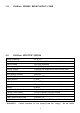
NO. PARAMETER NAME RANGE OF ADUSTMENT 14 CONTROL 17 ROTATION TERMINAL STRIP ONLY (01), REMOTE KEYPAD ONLY (02) FORWARD ONLY (01), FORWARD AND REVERSE (02) x0.1 (01), x1.0 (02), x10.0 (03) 0.1 - 990 SEC 0.1 - 990 SEC 0.0 - 990 SEC 0 - 30 % 0 - MAXIMUM FREQUENCY MINIMUM FREQUENCY - 99 Hz 30 - 180 % (NOTE 2) 30 - 100 % 25 - 99 Hz 0 - 30 % 0 - 20 % 0.0 - 5.0 % 0 - MAXIMUM FREQUENCY 0 - 10 Hz 0.
15.0 DESCRIPTION OF PARAMETERS 01 LINE VOLTAGE SELECTION This calibrates the drive for the actual applied input voltage, and can be set to HIGH (01) or LOW (02). Refer to the table below for the proper setting depending on the input voltage.
03 START METHOD WARNING! Automatic starting of equipment may cause damage to equipment and/or injury to personnel! Automatic start should only be used on equipment that is inaccessible to personnel. 01 NORMAL: The drive will start when the appropriate contact is closed on the terminal strip. See Section 11 for possible control configurations. 02 START ON POWER UP: The drive will automatically start upon application of input power.
04 STOP METHOD 01 COAST TO STOP: When a STOP command is given, the drive shuts off the output to the motor, allowing it to coast freely to a stop. 02 COAST WITH DC BRAKE: When a stop command is given, the drive will activate DC braking (after a delay of up to 2 seconds, depending on frequency) to help decelerate the load. Refer to Parameters: 21 - DC BRAKE TIME, and 22 - DC BRAKE VOLTAGE.
06 AT SET SPEED: Closes if the drive is within + 0.5 Hz of the speed setpoint. 07 ABOVE PRESET SPEED #3: Closes if the output frequency exceeds PRESET SPEED #3 (Parameter 33). Opens if the output frequency is equal to or less than PRESET SPEED #3. 08 CURRENT LIMIT: Closes if the output current exceeds the CURRENT LIMIT setting. Opens if the output current is equal to or less than CURRENT LIMIT (see Parameter 25).
08 DB FAULT: Sets TB-13A as a dynamic braking fault input when used with the optional dynamic braking module. When this input is activated by the dynamic braking module, the drive will trip into a "dF" fault and the motor will coast to a stop. Refer to the instructions included with the Dynamic Braking option. 09 AUXILIARY STOP: When TB-13A is opened with respect to TB-11, the drive will decelerate to a STOP (even if STOP METHOD is set to COAST) at the rate set into ACCEL/DECEL #2 (Parameter 42).
08 DB FAULT: Used with the optional dynamic braking module. When this input is activated by the dynamic braking module, the drive will trip into a "dF" fault and the motor will coast to a stop. Refer to the instructions included with the Dynamic Braking option. 09 AUXILIARY STOP: When TB-13B is opened with respect to TB-11, the drive will decelerate to a STOP (even if STOP METHOD is set to COAST) at the rate set into ACCEL/DECEL #2 (Parameter 42).
09 ACCEL/DECEL #2: Selects the acceleration and deceleration time programmed into ACCEL/ DECEL #2 (Parameter 42). NOTE: If the optional remote keypad is used, functions 02, 05, and 07 are disabled. Therefore, if this terminal is not being used for any of the other functions, it should be set to NONE (01). 14 CONTROL 01 TERMINAL STRIP ONLY: The drive will only respond to START and direction commands from the terminal strip.
19 ACCELERATION TIME This sets the acceleration rate for all of the speed reference sources (keypad, speed pot, jog, MOP, and preset speeds). This setting is the time to accelerate from 0 Hz to the BASE FREQUENCY (Parameter 27). This parameter is affected by the setting of TIME RANGE SELECT (Parameter 18). 20 DECELERATION TIME This sets the deceleration rate for all of the speed reference sources (keypad, speed pot, jog, MOP, and preset speeds).
When using a speed pot reference, this parameter also sets the drive speed that corresponds to the maximum analog input (10 VDC). NOTE: If this parameter is changed while the drive is running, the new value will not take effect until the drive is stopped. 25 CURRENT LIMIT This sets the maximum allowable output current of the drive. The maximum setting is either 180% or 150%, depending on whether LINE VOLTAGE SELECTION (Parameter 01) is set to HIGH or LOW.
28 FIXED BOOST FIXED BOOST increases starting torque by increasing the output voltage when operating below half of the base frequency, which increases the V/Hz ratio. For better out-of-the-box performance, SCN Series drives are shipped with a setting that is different from the factory default of 1%. Units rated 0.25 to 1 HP are set to 5.3%, units rated 1.5 to 2 HP are set to 4.4%, and 3 HP units are set to 3.6%. 29 ACCELERATION BOOST ACCELERATION BOOST helps accelerate high-inertia loads.
NOTE 2: When a TB-13 terminal is programmed for a function other than a preset speed select, it is considered OPEN for the table above. Preset Speed #6 and #7 can also be used as skip frequencies to restrict the drive from operating at frequencies that cause vibration in the system. See Parameter 38 below. 38 SKIP BANDWIDTH The SM-Basic drive has two skip frequencies that can be used to lock out critical frequencies that cause mechanical resonance in the system.
48 PROGRAM SELECTION This is used to select whether the drive will operate according to the user settings or the optional OEM default settings, and to reset the parameters to default settings. Refer to Section 13.2. 01 OPERATE WITH USER SETTINGS: The drive will operate according to the user settings. Operation in USER mode allows the parameter values to be changed to suit any application.
50 FAULT HISTORY The FAULT HISTORY stores the last eight faults that tripped the drive. Refer to Section 16.0 TROUBLESHOOTING for a list of the faults and possible causes. Use the s and t buttons to scroll through the fault entries. The faults are stored from newest to oldest, with the first fault shown being the most recent. The display will read “_ _” if the FAULT HISTORY does not contain any fault messages. 51 SOFTWARE VERSION This displays the software version number for the control board software.
57 TERMINAL STRIP STATUS This indicate the status of several terminals using the vertical segments of the LED display. An illuminated segment indicates that the particular terminal is closed to TB-2. TB-1 58 TB-13A TB-13C TB-13B TB-14 FACTORY RESERVED KEYPAD AND PROTECTION STATUS This indicate the status of the buttons on the keypad, and the status of the protective circuitry in the drive, using the horizontal segments of the LED display.
16.0 TROUBLESHOOTING To aid in troubleshooting, Parameters 50 through 58 can be accessed without entering the PASSWORD. Simply press the Mode button twice to “skip” over the PASSWORD prompt, and “50” will be displayed to indicate that the parameter menu has been entered and Parameter 50 (FAULT HISTORY) can be viewed. The s and t buttons can then be used to scroll from Parameter 50 to Parameter 58. Once the desired parameter is found, press the Mode button to view its “contents”.
The table below lists the fault conditions that will cause the drive to shut down, as well as some possible causes. Please contact the factory for more information on troubleshooting faults. FAULT MESSAGES FAULT DESCRIPTION & POSSIBLE CAUSES AF High Temperature Fault: Ambient temperature is too high; Cooling fan has failed (if equipped). CF Control Fault: A blank EPM, or an EPM with corrupted data has been installed. Perform a factory reset using Parameter 48 - PROGRAM SELECTION.
17.0 SM-Basic DISPLAY MESSAGES The following describes the various displays and messages that can appear on the SCN drive. 17.1 SPEED DISPLAY If the drive is in a STOP state (indicated by "- -" on the display), and the keypad speed command is changed, the display will show the commanded speed, and the upper left decimal point will turn on solid. About five seconds after a change is made, the display will begin to alternate between the commanded speed value and the "- -" display.
SPEED SOURCE DISPLAYS DISPLAY DESCRIPTION CP CONTROL PAD: Speed is set using the V and W buttons on the front of the drive. EU EXTERNAL VOLTAGE: Speed is controlled by a speed pot. JG JOG: The drive is in Jog mode, and the speed is set by Preset Speed #2 (Parameter 32). OP MOP (Motor Operated Pot): Contacts wired to two of the TB-13 terminals are used to increase and decrease the drive speed. See Parameters 10, 11, and 12.
18.0 USER SETTING RECORD NO. PARAMETER NAME FACTORY DEFAULT 01 LINE VOLTAGE HIGH (01) 02 CARRIER FREQUENCY 6 kHz (02) 03 START METHOD NORMAL (01) 04 STOP METHOD COAST (01) 05 STANDARD SPEED SOURCE KEYPAD (01) 06 TB-14 OUTPUT NONE (01) 10 TB-13A FUNCTION SELECT NONE (01) 11 TB-13B FUNCTION SELECT NONE (01) 12 TB-13C FUNCTION SELECT NONE (01) 14 CONTROL TERMINAL STRIP ONLY (01) 17 ROTATION FORWARD ONLY (01) 18 TIME RANGE SELECT x1.
NO.
Service Dept.