
User Manual

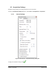

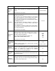


Table Of Contents
- List of Figures
- List of Tables
- 1. Introduction
- 1.1. Description
- 1.2. SPI Carrier Board
- 1.3. USB, CAN and SERIAL Carrier Board
- 1.4. Working Diagram
- 1.4.1. SPI Carrier Board
- 1.4.2. USB, CAN and SERIAL Board
- 2. Underlying Principles
- 3. Getting Started
- 3.1. Optional Power Supply
- 3.2. Optional SPI cable
- 3.3. Setup
- 3.4. Connecting to the LeddarVu Module
- 4. Measurements and Settings
- 4.1. Distance Measurement
- 4.2. Data Description
- 4.3. Acquisition Settings
- 4.3.1. General Settings
- 4.3.2. Enabling and Disabling Segments
- 4.4. Measurement Rate
- 4.5. CPU Load
- 5. Communication Interfaces
- 5.1. SPI Interface
- 5.1.1. SPI Basics
- 5.1.2. SPI Protocol
- 5.1.3. Memory Map
- Configuration Data
- Product Configuration
- Device Information and Constants
- LeddarVu Device Information and Constants
- General Status
- LeddarVu Status
- Detection List
- Transaction Configuration
- 5.1.4. SPI Operation
- 5.1.4.1. SPI Port Configuration
- 5.1.4.2. Sensor Hard Reset
- 5.1.4.3. Speed and timing
- 5.1.4.4. Access
- 5.1.4.5. Modification
- 5.2. I2C Interface
- 5.3. USB Interface
- 5.4. Serial Link Interface
- 5.5. CAN Bus Interface
- 6. Leddar™ Configurator
- 6.1. Introduction to Configurator Software
- 6.2. Connection Window
- 6.3. Leddar™ Configurator Main Window
- 6.3.1. Toolbar
- 6.3.2. Fit to Window
- 6.3.3. Force Equal Horizontal and Vertical Scales
- 6.3.4. Zoom in
- 6.3.5. Zoom out
- 6.3.6. Scale
- 6.3.7. Panning and Zooming
- 6.3.8. Changing the LeddarVu Module Origin
- 6.3.9. Changing the LeddarVu Module Orientation
- 6.4. Settings
- 6.4.1. Module Name
- 6.4.2. Acquisition Settings
- 6.4.3. Serial Port
- 6.4.4. CAN Port
- 6.5. Saving and Loading a Configuration
- 6.6. Configuring Detection Records
- 6.7. Using Detection Records
- 6.8. Data Logging
- 6.9. Firmware Update
- 6.10. Device State
- General
- Device Information
- Carrier
- 6.11. Preferences
- 6.12. Raw Detections
- 7. Specifications
- 7.1. General
- 7.2. Mechanical
- 7.3. Electrical
- 7.4. Optical
- 7.5. Performance
- 7.6. Regulatory Compliance and Safety
- 7.7. Dimensions
- 7.7.1. 98.5 Module
- 7.7.2. 47.5 Module
- 7.7.3. 16 Module
- 8. Technical Support
- Appendix A ̶ Example of a 0x04 function (read input register)
- Appendix B ̶ Example of a 0x41 Modbus Function
- Appendix C ̶ Example of a LeddarVu CAN Bus Detection Request

LeddarVu – User Guide Page 34 of 129
Parameter
Description
Range
Threshold
Offset
Modification to the amplitude threshold.
Higher values decrease the sensitivity and reduce the
range.
See below for more details.
−50.00 to 500.00
Smoothing
Object smoothing algorithm. Smooths the LeddarVu
module measurements.
The behavior of the smoothing algorithm can be adjusted
by a value ranging from -16 to 16. Higher values enhance
the module precision but reduce the module reactivity.
The smoothing algorithm can be deactivated by clearing
the Enable check box.
The measurement smoothing algorithm is advised for
application that need to measure slowly moving objects
with a high precision.
The application requiring to quickly track moving objects,
the smoothing should be configured with a value lower than
0 or simply deactivated.
See below for more details.
−16 to 16
Light Source
Control
Light source power control options.
Selects between manual and automatic power control. In
automatic, light source power is adjusted according to
incoming detection amplitudes.
The current laser power level is visible in the
View > State > Device State window.
See below for more details.
100%
81%
53%
28%
6%
Change Delay
(Channel and
Frame)
Minimum delay between power changes.
Smaller numbers speed up the response time of the light
source power adjustment.
Channel:
0 to 8
Frame: Varies
Saturation
Compensation
When selected, this parameter activates the advanced
distance computation algorithm for very strong (saturated)
signals. This computation uses slightly more computing
power to enhance the quality of the distance
measurements of saturated light pulses.
N/A
Static Noise
Removal
When selected, this parameter enhances measurements
by subtracting the constant electronic noise present at the
beginning of signals.
N/A
Overshoot
Management
When selected, this parameter improves the detection of
false measurements caused by specific signal shapes. For
example, this may occur when strongly reflecting objects
are present in the field of view.
N/A