
User Manual

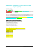

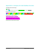
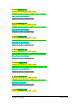
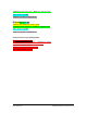


Table Of Contents
- List of Figures
- List of Tables
- 1. Introduction
- 1.1. Description
- 1.2. SPI Carrier Board
- 1.3. USB, CAN and SERIAL Carrier Board
- 1.4. Working Diagram
- 1.4.1. SPI Carrier Board
- 1.4.2. USB, CAN and SERIAL Board
- 2. Underlying Principles
- 3. Getting Started
- 3.1. Optional Power Supply
- 3.2. Optional SPI cable
- 3.3. Setup
- 3.4. Connecting to the LeddarVu Module
- 4. Measurements and Settings
- 4.1. Distance Measurement
- 4.2. Data Description
- 4.3. Acquisition Settings
- 4.3.1. General Settings
- 4.3.2. Enabling and Disabling Segments
- 4.4. Measurement Rate
- 4.5. CPU Load
- 5. Communication Interfaces
- 5.1. SPI Interface
- 5.1.1. SPI Basics
- 5.1.2. SPI Protocol
- 5.1.3. Memory Map
- Configuration Data
- Product Configuration
- Device Information and Constants
- LeddarVu Device Information and Constants
- General Status
- LeddarVu Status
- Detection List
- Transaction Configuration
- 5.1.4. SPI Operation
- 5.1.4.1. SPI Port Configuration
- 5.1.4.2. Sensor Hard Reset
- 5.1.4.3. Speed and timing
- 5.1.4.4. Access
- 5.1.4.5. Modification
- 5.2. I2C Interface
- 5.3. USB Interface
- 5.4. Serial Link Interface
- 5.5. CAN Bus Interface
- 6. Leddar™ Configurator
- 6.1. Introduction to Configurator Software
- 6.2. Connection Window
- 6.3. Leddar™ Configurator Main Window
- 6.3.1. Toolbar
- 6.3.2. Fit to Window
- 6.3.3. Force Equal Horizontal and Vertical Scales
- 6.3.4. Zoom in
- 6.3.5. Zoom out
- 6.3.6. Scale
- 6.3.7. Panning and Zooming
- 6.3.8. Changing the LeddarVu Module Origin
- 6.3.9. Changing the LeddarVu Module Orientation
- 6.4. Settings
- 6.4.1. Module Name
- 6.4.2. Acquisition Settings
- 6.4.3. Serial Port
- 6.4.4. CAN Port
- 6.5. Saving and Loading a Configuration
- 6.6. Configuring Detection Records
- 6.7. Using Detection Records
- 6.8. Data Logging
- 6.9. Firmware Update
- 6.10. Device State
- General
- Device Information
- Carrier
- 6.11. Preferences
- 6.12. Raw Detections
- 7. Specifications
- 7.1. General
- 7.2. Mechanical
- 7.3. Electrical
- 7.4. Optical
- 7.5. Performance
- 7.6. Regulatory Compliance and Safety
- 7.7. Dimensions
- 7.7.1. 98.5 Module
- 7.7.2. 47.5 Module
- 7.7.3. 16 Module
- 8. Technical Support
- Appendix A ̶ Example of a 0x04 function (read input register)
- Appendix B ̶ Example of a 0x41 Modbus Function
- Appendix C ̶ Example of a LeddarVu CAN Bus Detection Request

LeddarVu – User Guide Page 124 of 129
(1) 25 00 52 81 09 07:
Distance (cm): 00 25 hex = 37cm = 0.37m
Amplitude (count): 81 52 hex = 33106 / 64 = 517.28 counts
Flag: 09 hex = 9 (Saturation)
Segment #: 07 hex = 7 (Segment #8)
(2) 25 00 49 81 09 06:
Distance (cm): 00 25 hex = 37cm = 0.37m
Amplitude (count): 81 49 hex = 33097 / 64 = 517.14 counts
Flag: 09 hex = 9 (Saturation)
Segment #: 06 hex = 6 (Segment #7)
(3) 24 00 4F 81 09 05:
Distance (cm): 00 24 hex = 36cm = 0.36m
Amplitude (count): 81 4F hex = 33103 / 64 = 517.23 counts
Flag: 09 hex = 9 (Saturation)
Segment #: 05 hex = 5 (Segment #6)
(4) 25 00 05 81 09 04:
Distance (cm): 00 25 hex = 37cm = 0.37m
Amplitude (count): 81 05 hex = 33029 / 64 = 516.08 counts
Flag: 09 hex = 9 (Saturation)
Segment #: 04 hex = 4 (Segment #5)
(5) 29 00 A9 7D 09 03:
Distance (cm): 00 29 hex = 41cm = 0.41m
Amplitude (count): 7D A9 hex = 32169 / 64 = 502.64 counts
Flag: 09 hex = 9 (Saturation)
Segment #: 03 hex = 3 (Segment #4)
(6) 2E 00 96 66 01 02:
Distance (cm): 00 2E hex = 46cm = 0.46m
Amplitude (count): 66 96 hex = 26262 / 64 = 410.34 counts
Flag: 01 hex = 1 (Valid)
Segment #: 02 hex = 2 (Segment #3)
(7) 35 00 CC 47 01 01:
Distance (cm): 00 35 hex = 53cm = 0.53m