
User Guide
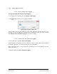

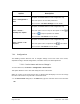


Table Of Contents
- Table of Contents
- Version History
- List of Figures
- List of Tables
- Contact Information
- Document Conventions
- 1. Label Explanation and Safety Information
- 1.1. Regulatory Compliance
- 2. Introduction
- 2.1. Definitions
- 2.2. Underlying Principles and LiDAR Fundamentals
- 2.3. Key Factors for Best Sensor Performance
- 3. Description
- 3.1. Equipment Designation and Description
- 3.1.1. Key Components
- 3.1.2. Distance Measurement
- 4. Specifications
- 4.1. General Characteristics
- 4.2. Mechanical Specifications
- 4.2.1. Leddar T16 Traffic Dimensions
- 4.2.2. Leddar T16 Tolling Dimensions
- 4.2.3. Distance Screw
- 4.3. Electrical Specifications
- 4.4. Environmental Specifications
- 4.5. Software System Requirements
- 5. Installing the Leddar T16 Sensor
- 5.1. Installing and Orienting the Sensor
- 5.2. Connecting the Leddar T16 Sensor
- 6. Installing LeddarTM Configuration
- 6.1. Connecting to LeddarTM Configuration
- 7. LeddarTM Configuration
- 7.1. Main Windows, Menus and Buttons
- 7.2. File Menu
- 7.2.1. Recordings (.ltl file)
- 7.2.1.1. How to Edit Recording Settings
- 7.2.1.2. How to Record a Scene
- 7.2.1.3. How to Play a Recording
- 7.2.1.4. How to Extract a Scene Segment
- 7.2.2. Data Logging (.txt file)
- 7.2.2.1. How to Setup Data Logging
- 7.2.2.2. How to Start and Stop Data Logging
- 7.3. Device Menu
- 7.3.1. Configurations
- 7.3.1.1. Device Name and How to Change it
- 7.3.2. Acquisition Settings
- 7.3.3. Network Settings
- 7.3.4. Orientation Control (Pan/Tilt Adjustment)
- 7.3.5. Video Settings
- 7.3.6. Action
- 7.4. View Menu
- 7.4.1. Device State
- 7.4.2. Image Activation
- 7.4.3. Grid Activation
- 7.4.4. Raw Detections
- 7.4.5. Raw Detections Graph
- 7.4.5.1. Setting Scale Areas and Detection Points
- 7.4.5.2. Detection Scene Short Keys
- 7.5. Settings Menu
- 7.5.1. Record Settings
- 7.5.2. Data Logger
- 7.5.3. Preferences
- 7.5.4. Access Level
- 7.6. Help Menu
- 7.6.1. User Guide
- 7.6.2. LeddarTM SDK Help
- 7.6.3. About
- 8. Communication Protocol
- 9. Troubleshooting
- 10. Maintenance
- 11. Warranty
- 12. Technical Support
- 13. Index
- Appendix A. Static IP and DHCP Configuration Under Windows 7 and Up
- Appendix B. Making Connectors for the Ethernet Cable
- Appendix C. Procedure to Use LeddarCDemo (SDK Code Example) with the Leddar T16 Sensor

Page 55 of 109 Leddar T16 – User Guide
Table 21: Acquisition Settings Window
Parameter
Description
Range
Crosstalk
Removal
Inter-segment interference noise removal.
Crosstalk is a phenomenon inherent to all multiple segments
time-of-flight sensors. It causes a degradation of the distance
measurement accuracy of an object when one or more objects
with significantly higher reflectivity are detected in other
segments at a similar distance.
Enable
Disable
Static Noise
Removal
When selected, this parameter enhances measurements by
subtracting the constant electronic noise present at the
beginning of signals.
Enable
Disable
Pulse Width
Compensation
The objects in the sensor field of detection create a signature
in the full-waveform signal called pulses. The pulse detector
analyzes the full-waveform signal to recognize these pulses
and compute their distance. By nature, time-of-flight sensor
using full-waveform analysis can detect several distinct objects
with a single photodiode element.
The detected pulses have specific amplitudes based on their
distance from the sensor and on the reflectivity of the objects.
It is well known that pulses of small amplitudes do not lead to
accurate and precise distance measurements. Consequently,
the algorithm removes all pulses with amplitudes under a given
threshold. This threshold depends on the acquisition settings
of the sensor.
Enable
Disable
Overshoot
Management
When selected, this parameter improves the detection of
false measurements caused by specific signal shapes. For
example, this may occur when strongly reflecting objects are
present in the field of view.
Enable
Disable
Saturation
Compensation
When selected, this parameter activates the advanced
distance computation algorithm for very strong (saturated)
signals. This computation uses slightly more computing power
to enhance the quality of the distance measurements of
saturated light pulses.
The algorithm classifies the detected pulses based on their
shape. The sensor determines which pulses are saturated and
which have a normal shape. Saturated pulse occurs when the
signal backscattered by the object is so strong that the full-
waveform signal is clipped. If not treated, this phenomenon
creates an important degradation of the distance
measurement accuracy. It is why a saturation compensation
algorithm is executed when saturated pulses are detected.
Enable
Disable