
Manual


Leddar™One Sensing Module 7
The power and interface signals are included on a six-pin standard 0.1” pitch
header with the following pinout:
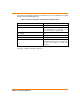
Table 1: Pinout of the Power and Interface Signals Header
Pin – Function
Description
1 – GND
Ground.
2 – IRQ
Interrupt Signal, active high. Set when a
new measurement is available, reset
when data read from Modbus link.
3 – Supply
5V
4 – RX or RS-485+
Serial port input.
5 – TX or RS-485-
Serial port output.
6 – RESET_N
This is a pulled-up input that must be
pulled down below 0.8 V for at least 350
ns and then released to reset the
processor.
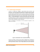
The pin 1 position is shown in Figure 1.