
User Manual
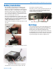

Digital Hybrid Wireless Belt-Pack Transmitter
Rio Rancho, NM
9
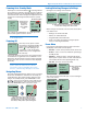
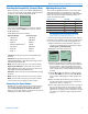
Selecting the Compatibility (Compat) Mode
When used with a Lectrosonics Digital Hybrid Wireless
®
receiver, the best audio quality will be achieved with the
system set to the Hybrid compatibility mode.
Compat
Hybrid
Gain
Freq.
ProgSw
Compat
Use the UP and DOWN arrows to select the desired
mode, then press the BACK button twice to return to
the Main Window.
Compatibility modes are as follows:
Receiver Models LCD menu item
• 100Series: 100Mode
• 200Series: 200Mode
• Mode3:* Mode3
• DigitalHybridWireless
®
: Hybrid
• IFBSeries: IFBMode
• Mode6:* Mode6
• Mode7:* Mode7
100 Series works with Lectrosonics UCR100 analog
receivers.
200 Series works with Lectrosonics earlier
UCR201/205/210D/211 and UCR195 analog receivers
with dual band compandors.
Mode 3* works with certain non-Lectrosonics models.
Digital Hybrid Wireless
®
works with all Lectrosonics
Digital Hybrid receivers. The receiver must also be set
to the Digital Hybrid compatibility mode.
IFB Series works with Lectrosonics IFB R1/R1a analog
receivers.
Mode 6* works with certain non-Lectrosonics models.
Mode 7* works with certain non-Lectrosonics models.
*Contactthefactoryfordetailsofthesemodes
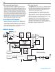
Connecting the Signal Source
Microphones, line level audio sources and instruments
can be used with the transmitter. Refer to the section
entitled Wiring Hookups for Different Sources for
details on the correct wiring for microphones to take full
advantage of the Servo Bias circuitry.
Adjusting the Input Gain
The two bicolor Modulation LEDs on the control panel
and keypad provide a visual indication of the audio
signal level entering the transmitter. The LEDs will glow
either red or green to indicate modulation levels as
shown in the following table.
Signal Level -20 LED -10 LED
Less than -20 dB Off Off
-20 dB to -10 dB Green Off
-10 dB to +0 dB Green Green
+0 dB to +10 dB Red Green
Greater than +10 dB Red Red
NOTE: Full modulation is achieved at 0 dB, when
the “-20” LED first turns red. The limiter can cleanly
handle peaks up to 30 dB above this point.
It is best to go through the following procedure with the
transmitter in the standby mode so that no audio will en-
ter the sound system or recorder during adjustment.
1) With fresh batteries in the transmitter, power the
unit on in the standby mode (see previous section
Powering On in Standby Mode).
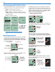
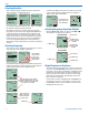
2) Navigate to the Gain setup screen.
-40
-20
0
Gain
25
Gain
Freq.
ProgSw
Compat
3) Prepare the signal source. Position a microphone
the way it will be used in actual operation and have
the user speak or sing at the loudest level that oc-
cur during use, or set the output level of the instru-
ment or audio device to the maximum level that will
be used.
4) Use the and arrow buttons to adjust the gain
until the –10 dB glows green and the –20 dB LED
starts to flicker red during the loudest peaks in the
audio.
5) Once the audio gain has been set, the signal can
be sent through the sound system for overall level
adjustments, monitor settings, etc.
6) If the audio output level of the receiver is too high or
low, use only the controls on the receiver to make
adjustments. Always leave the transmitter gain ad-
justment set according to these instructions, and do
not change it to adjust the audio output level of the
receiver.