
User Manual

LMb
LECTROSONICS, INC.
2
Consumer Alert for US Users - FCC Order DA 10-92
Most users do not need a license to operate this wireless microphone system. Nevertheless, operating this micro-
phone system without a license is subject to certain restrictions: the system may not cause harmful interference; it
must operate at a low power level (not in excess of 50 milliwatts); and it has no protection from interference received
from any other device. Purchasers should also be aware that the FCC is currently evaluating use of wireless mi-
crophone systems, and these rules are subject to change. For more information, call the FCC at 1-888- CALL-FCC
(TTY: 1-888-TELL-FCC) or visit the FCC’s wireless microphone website at www.fcc.gov/cgb/wirelessmicrophones.
To operate wireless microphone systems at power greater than 50mW, you must qualify as a Part 74 user and be
licensed. If you qualify and wish to apply for a license go to: http://www.fcc.gov/Forms/Form601/601.html
Table of Contents
Introduction ............................................................................ 3
About Digital Hybrid Wireless .............................................. 3
Frequency Agility.................................................................. 3
Wide-Band Deviation ........................................................... 3
Servo Bias Input and Wiring ................................................ 3
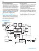
LMb Block Diagram .............................................................. 4
DSP-controlled Input Limiter ................................................ 4
No Pre-Emphasis/De-Emphasis .......................................... 4
Pilot Tone Squelch ............................................................... 4
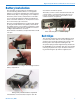
Battery Installation ................................................................ 5
Belt Clips ................................................................................ 5
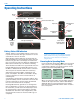
Operating Instructions .......................................................... 6
Battery Status LED Indicators .............................................. 6
Powering On in Operating Mode .......................................... 6
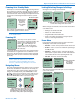
Powering On in Standby Mode ............................................ 7
Powering Off ........................................................................ 7
Navigating Menus ................................................................ 7
Locking/Unlocking Changes to Settings............................... 7
Power Menu ......................................................................... 7
Selecting Programmable Switch Functions.......................... 8
Main Window Indicators ....................................................... 8
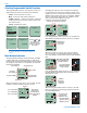
Selecting the Compatibility (Compat) Mode ......................... 9
Connecting the Signal Source ............................................. 9
Adjusting the Input Gain ....................................................... 9
Selecting Step Size ............................................................ 10
Selecting Frequency .......................................................... 10
Selecting Frequency Using Two Buttons ............................ 10
Helpful Features on Receivers ........................................... 10
About Overlapping Frequency Blocks ................................ 11
Selecting Audio Polarity (Phase) ........................................ 11
Adjusting LCD Backlight .................................................... 11
RF ON/OFF on the Menu ................................................... 11
Selecting Battery Type ....................................................... 11
Restoring Default Settings ................................................. 11
IR (infrared) Sync ............................................................... 11
5-Pin Input Jack Wiring ....................................................... 12
Microphone Cable Termination
for Non-Lectrosonics Microphones ............................ 13
Input Jack Wiring for Different Sources ............................ 14
Compatible Wiring for Both Servo Bias Inputs
and Earlier Transmitters: .................................................... 14
Simple Wiring for Servo Bias Inputs ONLY: ........................ 14
Microphone RF Bypassing ................................................. 15
Line Level Signals .............................................................. 15
Wiring Diagram for MI39A Instrument Cable ..................... 15
Accessories ......................................................................... 16
Troubleshooting ................................................................... 17
Specifications and Features ............................................... 18
Service and Repair .............................................................. 19
Returning Units for Repair ................................................. 19