
User Manual - RCVR


LR
LECTROSONICS, INC.
8
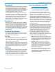
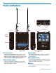
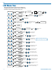
LCD Main Window
RF level Diversity
activity
Pilot
tone
Frequency
band in use
Audio
level
Transmitter battery
elapsed time
Frequency
in MHz
Frequency
in hex code
Full
modulation
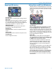
RF level
The triangle graphic corresponds to the scale on the
left side of the display. The scale indicates the incom-
ing signal strength in microvolts, from 1 uV at the bot-
tom to 1,000 uV (1 millivolt) at the top.
Diversity activity
This icon flips upside down and back as the SmartDi-
versity antenna phase combining circuitry operates.
Pilot tone
This icon will appear in compatibility modes where a
supersonic pilot tone is used in squelch control. The
icon will blink if a pilot is expected but not present on
the incoming signal.
Frequency in MHz
The example here shows the frequency expressed in
MHz (megahertz) when the StepSize is set to 100 kHz.
When the StepSize is set to 25 kHz, the display will
include three numerals to the right of the decimal point.
Frequency in hex code
The characters (CD in the above example) indicate
the frequency expressed with hexadecimal numerals
to simplify backward compatibility with older transmit-
ters that use two rotary switches to set the operating
frequency. See About Frequency Blocks on the next
page for more information.
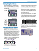
Frequency block in use
The tuning range of the receiver covers three standard
frequency blocks. The hex code numbers are repeated
in each block, so the block number must be associated
with the hex code number to define a frequency.
Transmitter battery elapsed time
A timer is included to monitor the runtime of the trans-
mitter, which is especially useful when using recharge-
able batteries. The timer runs whenever a valid signal
is being received from the transmitter, and stops when
the signal is no longer being received. The display
shows the accumulated runtime in hours and minutes.
Audio level
This bar graph indicates the level of the audio entering
the transmitter. The “0” at the right side of the graph
indicates full modulation and the onset of limiting.
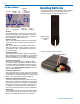
Installing Batteries
Power is provided by two AA batteries. Alkaline, lithium
or NiMH types can be used. The batteries are con-
nected in series by a plate in the battery door.
Slide the battery
door outward to
open it
Polarity is marked on the rear panel.
Polarity markings