
User Manual - RCVR


LR
LECTROSONICS, INC.
4
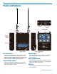
Introduction
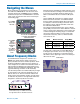
Three Band Tuning Range
The LR receiver tunes across a range of over 76 MHz.
This tuning range covers three standard Lectrosonics
frequency bands. See page 9 for more information.
TUNING RANGE
BAND
BAND
BAND
Three tuning ranges are available covering standard
bands as follows:
Band Bands Covered Freq. (MHz)
A1 470, 19, 20 470.1 - 537.5
B1 21, 22 23 537.6 - 614.3
C1 24, 25, 26 614.4 - 691.1
To simplify backward compatibility with earlier Digital
Hybrid Wireless
®
equipment, band numbers are pre-
sented along with frequencies in LCD screens.
RF Front-End with Tracking Filter
A wide tuning range is helpful in finding clear frequen-
cies for operation, however, it also allows a greater
range of interfering frequencies to enter the receiver.
The UHF frequency band, where almost all wireless
microphone systems operate, is heavily populated
by high power TV transmissions. The TV signals are
immensely more powerful than a wireless microphone
transmitter signal and will enter the receiver even when
they are on significantly different frequencies than the
wireless system. This powerful energy appears as
noise to the receiver, and has the same effect as the
noise that occurs with extreme operating range of the
wireless system (noise bursts and dropouts). To allevi-
ate this interference, front-end filters are needed in the
receiver to suppress RF energy below and above the
operating frequency.
The LR receiver employs a variable frequency, track-
ing filter in the front-end section (the first circuit stage
following the antenna). As the operating frequency is
changed, the filters re-tune to stay centered over the
selected carrier frequency.
BAND
BAND
BAND
In the front-end circuitry, a tuned filter is followed by an
amplifier and then another filter to provide the selec-
tivity needed to suppress interference, yet provide a
wide tuning range and retain the sensitivity needed for
extended operating range.
IF Amplifiers and SAW Filters
The first IF stage employs two SAW (surface acoustic
wave) filters. The use of two filters significantly increas-
es the depth of filtering while preserving sharp skirts,
constant group delay, and wide bandwidth. Though
expensive, this special type of filter allows primary
filtering as early as possible, at as high a frequency as
possible, before high gain is applied, to deliver maxi-
mum image rejection. Since these filters are made of
quartz, they are very temperature stable.
The signal is converted to 243.950 MHz in the first
mixer stage, then passed through two SAW filters. Af-
ter the SAW filter, the IF signal is converted to 250 kHz
and then the majority of the gain is applied. Although
these IF frequencies are unconventional in a wide
deviation (±75 kHz) system, the design provides excel-
lent image rejection.
Digital Pulse Counting Detector
Following the IF section, the receiver uses an elegantly
simple, yet highly effective digital pulse counting
detector to demodulate the FM signal to generate the
audio, rather than a conventional quadrature detector.
This unusual design eliminates thermal drift, improves
AM rejection, and provides very low audio distortion.
The output of the detector is fed to the microprocessor
where a window detector is employed as part of the
squelch system.
DSP-Based Pilot Tone
The Digital Hybrid system design uses a DSP gener-
ated ultrasonic pilot tone to reliably mute the audio
when no RF carrier is present. The pilot tone must be
present in conjunction with a usable RF signal before
the audio output will be enabled. 256 pilot tone fre-
quencies are used across each 25.6 MHz band within
the tuning range of the system. This alleviates errone-
ous squelch activity in multichannel systems where a
pilot tone signal can appear in the wrong receiver via
IM (intermodulation).
Pilot tones are also provided for legacy equipment and
some models from other manufacturers.
Note: This description applies only to the Digital
Hybrid mode. In Lectrosonics 200 Series, IFB
and Mode 6 compatibility, only one pilot tone
frequency is used on all frequencies, emulating
the original crystal-based system. In other
compatibility modes, no pilot tone is used.