
User Manual - RCVR


LR
LECTROSONICS, INC.
14
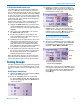
5) Set Up Transmitter to Matching Frequency
and Compatibility Mode
If you have not already set the frequency on the
transmitter in the previous procedures, use IR Sync or
complete the settings manually.
Lectrosonics transmitters with IR Sync:
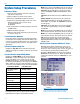
On the LR receiver, navigate to IR Sync on the menu
and press the MENU/SEL button. Hold the transmitter
and receiver fairly close to each other (within two feet
or so) and position them so the IR ports are facing one
another. Press the UP arrow on the receiver to initiate
the transfer of settings. The receiver will display a mes-
sage when the settings have been received.
Other transmitters:
Frequency, input gain, etc, are set with the controls on
the transmitter. The correct compatibility mode must
also be selected on the receiver.
6) Adjust Transmitter Input Gain
NOTE: This adjustment is very important, since
it will determine the signal to noise ratio and
dynamic range that the system will deliver.
Lectrosonics transmitters with LCD interface:
The LEDs on the control panel provide an accurate
indication of modulation level to assist in adjusting the
input gain. The LEDs will glow either red or green to
indicate modulation levels as shown in the following
table. Full modulation is achieved at 0 dB, when the
“-20” LED first turns red. The limiter can cleanly handle
peaks up to 30 dB above this point.
Signal Level -20 LED -10 LED
Less than -20 dB Off Off
-20 dB to -10 dB Green Off
-10 dB to +0 dB Green Green
+0 dB to +10 dB Red Green
Greater than +10 dB Red Red
NOTE: It is best to go through the following
procedure with the transmitter in the standby
mode so that no audio will enter the sound
system or recorder during adjustment.
1) With fresh batteries in the transmitter and power
the unit on in the standby mode (a brief press on
the power switch with L-Series transmitters).
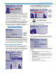
2) Navigate to the Gain setup screen.
Gain
LineIn
Freq.
ProgSw
-40
-20
0
Gain
25
3) Prepare the signal source. Position a microphone
the way it will be used in actual operation and have
the user speak or sing at the loudest level that
will occur during use, or set the output level of the
instrument or audio device to the maximum level
that will be used.
4) Use the and arrow buttons to adjust the gain
until the –10 dB glows green and the –20 dB LED
starts to flicker red during the loudest peaks in the
audio.
5) Once the transmitter input gain has been set, the
signal can be sent to the sound system or recorder
for level adjustments, monitor settings, etc.
6) Do not use the transmitter input gain control to
adjust the audio output level of the receiver.
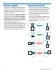
Other Transmitters:
Earlier Lectrosonics transmitters provide LEDs to ac-
curately indicate full modulation, with continuously vari-
able gain controls for a precise adjustment. The LEDs
operate in the same manner as those shown here for
transmitters with an LCD interface.
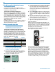
The UM400A transmitter shown below is typical of
many legacy Lectrosonics models.
LECTROSONICS
UM400a
OFF
ON
AUDIO
LEVEL
–10
–20
ANTENNA
Input gain
control
Modulation
level LEDs
Some transmitters from brands other than Lectroson-
ics can also be used if the appropriate compatibility
mode set is set in the receiver. Observe the audio level
meter on the LR receiver LCD as you adjust the input
gain on the transmitter to see the modulation level.
Some models may have limiters on the input to sup-
press overload distortion, and others may not. Monitor
the audio, preferably with headphones, as you adjust
the input gain to find the maximum level that can be
set without audible limiting or overload distortion.