
User Manual - HMA


Wideband Digital Hybrid
®
Plug-On Transmitter
Rio Rancho, NM
5
Low Frequency Roll-Off
The low frequency roll-off can be set for a 3 dB down
point at 35, 50, 70, 100, 120 and 150 Hz to control
subsonic and very low frequency audio content in
the audio. The actual roll-off frequency will vary slightly
depending upon the low frequency response of the
microphone.
Excessive low frequency content can drive the trans-
mitter into limiting, or in the case of high level sound
systems, even cause damage to loudspeaker systems.
The roll-off is normally adjusted by ear while listening
as the system is operating.
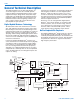
Input Limiter
A DSP-controlled analog audio limiter is employed
before the analog-to-digital (A-D) converter. The limiter
has a range of more than 30 dB for excellent overload
protection. A dual release envelope makes the limiter
acoustically transparent while maintaining low distor-
tion. It can be thought of as two limiters in series, a
fast attack and release limiter followed by a slow attack
and release limiter. The limiter recovers quickly from
brief transients, with no audible side effects, and also
recovers slowly from sustained high levels, to keep
audio distortion low and while preserving short term
dynamics.
Signal Encoding and Pilot Tone
In addition to controlling the limiter, the DSP also
encodes the digitized audio from the A-D converter
and adds an ultrasonic pilot tone to control the re-
ceiver’s squelch. A pilot tone squelch system provides
a reliable method of keeping a receiver output muted
(squelched) even in the presence of significant inter-
ference. When the system is operating in the hybrid
mode, a different pilot tone frequency is generated
for each carrier frequency in 100 kHz increments to
prevent inadvertent squelch problems and simplify
multi-channel coordination.
Microprocessor and DSP
A microprocessor monitors user command inputs from
the control panel buttons and numerous other internal
signals. It works intimately with the DSP to ensure the
audio is encoded according to the selected Compatibil-
ity Mode and that the correct pilot tone is added to the
encoded signal.
Compatibility Modes
The transmitter was designed to operate with Lectro-
sonics Digital Hybrid Wirteless
®
receivers and will yield
the best performance when doing so. However, due to
the flexibility of digital signal processing, the transmit-
ters can also operate in various compatibility modes
for use with Lectrosonics 100 and 200 Series and IFB
receivers. It will also work with certain non-Lectroson-
ics receivers. Contact your sales representative or the
factory for a complete list of compatible non-Lectroson-
ics receivers.
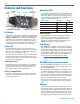
Control Panel
The control panel includes four membrane switches and
an LCD screen to adjust the operational settings. Multi-
color LEDs are used to indicate audio signal levels for
accurate gain adjustment and for battery status.
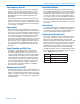
Frequency Blocks and Bands
Lectrosonics established a “block” numbering system
years ago to organize the range of frequencies avail-
able from the low 500 MHz band to the upper 700
MHz band. Each block includes 256 frequencies in 100
kHz increments. The block number is part of a simple
formula to derive the frequency. The block number is
multiplied by 25.6 to produce the lowest frequency in
the block. For example, block 27 x 25.6 = 691.200.
The HMa transmitter features a wideband tuning range
that covers three blocks. This tuning range is referred
to as a BAND rather than a block.
Band Tuning Range (MHz)
A1 470.100 - 534.575
B1 537.600 - 614.375
C1 614.400 - 691.175