
User's Manual


Watertight Transmitter
Rio Rancho, NM
5
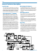
Signal Encoding and Pilot Tone
In addition to controlling the limiter, the DSP also en-
codes the digitized audio from the A/D converter and
adds an ultrasonic pilot tone to control the squelch in
the receiver. A pilot tone squelch system provides a reli-
able method of keeping a receiver output muted (audio
mute) even in the presence of significant interference.
When the system is operating in the hybrid mode, a
different pilot tone frequency is generated for each car-
rier frequency to prevent inadvertent squelch problems
in multi-channel sytems.
Microprocessor Control
A microprocessor monitors user command inputs from
the control panel buttons and numerous other internal
signals. It works intimately with the DSP to ensure the
audio is encoded according to the selected Compatibil-
ity Mode and that the correct pilot tone is added to the
encoded signal.
Compatibility Modes
The transmitter operates with Lectrosonics Digital
Hybrid receivers and will yield the best performance
when doing so, however, due to the flexibility of digital
signal processing, the transmitter can also operate in
various compatibility modes for use with Lectrosonics
200 Series, Lectrosonics 100 Series, IFB and certain
non-Lectrosonics receivers. Contact the Lectrosonics
sales department for more information about non-Lec-
trosonics receivers.
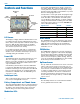
Control Panel
The control panel includes four membrane switches and
an LCD screen to adjust the operational settings. Multi-
color LEDs are used to indicate audio signal levels for
accurate gain adjustment and for battery status.
Wide-Band Deviation
±75 kHz deviation improves the signal to noise ratio and
audio dynamic range of a wireless system dramatically,
compared to other designs that use ±30 kHz to 40 kHz
deviation. Wide deviation combined with a high pow-
ered transmitters makes a significant improvement in
signal to noise ratio and operating range.
Variable Power Output
This advanced feature allows the operator to optimize
the transmitter for maximum battery life, or for maxi-
mum operating range. Power output is selected using
the LCD in a setup mode while the RF output of the
transmitter is turned off.
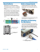
Battery Operation
Switching power supplies convert battery voltages to
operate various circuit stages with maximum efficiency.
The firmware “remembers” the settings when the bat-
teries are exhausted. After new batteries are installed,
a quick press of the AUDIO and FREQ buttons will turn
the power back on and return to the previous settings.
This is a unique behavior that takes place only when
the batteries fail during operation. If the unit is turned
off manually, a quick press of the buttons will turn it on
in the “standby” mode instead.
Because the battery caps make contact with the bat-
tery before the cap is seated, the power does not turn
back on automatically. This allows both batteries to
be installed and the caps tightened before power is
restored.
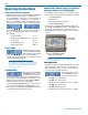
Frequency Blocks
Lectrosonics established a “block” numbering system
years ago to organize the range of frequencies avail-
able from the low end at 470.1 MHz band to the upper
end at 691.1 MHz. Each block includes 256 frequen-
cies in 100 kHz steps, which is the maximum switching
range of the transmitters.
Circulator/Isolator
The RF output circuit includes a magnetically polar-
ized ferrite called an isolator that blocks RF signals
entering the transmitter antenna from external sources
from traveling back into the final amplifier. This greatly
reduces RF intermodulation produced when multiple
transmitters are used in close proximity to one another
(several feet apart). The isolator also provides addition-
al RF output stage protection against static shock.