
User's Manual


WM, WM/E01, WM/E02, WM/X
LECTROSONICS, INC.
12
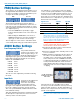
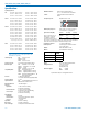
FREQ Button Settings
The frequency can be displayed either in MHz or as a
two-digit hexadecimal number and it can be set when
the unit is in “standby” or when the transmitter is pow-
ered up in the normal operating mode.
MHz Hex Code
The hexadecimal numbering system is unique to
Lectrosonics where two alphanumeric characters cor-
respond to the left and right switch settings on earlier
analog transmitters that had mechanical rotary switch-
es to adjust frequency.
• Press the FREQ button repeatedly to toggle
between either the MHz screen or the Hex Code
screen.
• While holding the FREQ button, use the UP or
DOWN arrow buttons to move the operating fre-
quency up or down from the current setting.
The two-digit hex code is easier to remember, which
can be handy when setting up a multi-channel system.
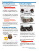
AUDIO Button Settings
Low Frequency Roll-off
It is possible that the low
frequency roll-off point could
affect the gain setting, so it’s
generally good practice to make this adjustment before
adjusting the input gain. Press and hold the AUDIO
button while selecting the desired roll-off frequency
with the UP and DOWN arrows.
• LF 35 35 Hz
• LF 50 50 Hz
• LF 70 70 Hz
• LF 100 100 Hz
• LF 120 120 Hz
• LF 150 150 Hz
The roll-off is often adjusted by ear while monitoring
the audio.
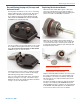
Input Gain
Properly set, this adjustment
maximizes the signal to
noise ratio of the system,
and prevents loud peaks from being distorted. The
input gain can be adjusted with the unit in the “stand-
by” mode or while powered up in normal operation.
The control panel Modulation LEDs indicate the audio
level and limiter activity.
This gain adjustment matches the transmitter gain with
the microphone’s output level, the user’s voice level
and the position of the microphone.
It is desirable to to set the gain so that some limiting
occurs on louder peaks. The limiter is very transparent
and its effect is not audible until the system is close to
overload. In other words, don’t be shy about turning
up the gain. You can turn the gain up to maximum and
listen for distortion or compression to get a feel for how
much headroom is available.
Signal Level -20 LED -10 LED
Less than -20 dB
Off Off
-20 dB to -10 dB
Green Off
-10 dB to +0 dB Green Green
+0 dB to +10 dB Red Green
Greater than +10 db
Red Red
Note: Different voices will usually require
different gain settings, so check this adjustment
as each new person uses the system. If several
different people will be using the transmitter and
there is not time to make the adjustment for each
individual, adjust it for the loudest voice.
Warning: If the wireless system is connected
to a live sound system, turn the sound system
level down first to avoid severe feedback.
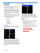
1) Position the microphone in the location where it
will be used in actual operation.
2) Place the transmitter in the “standby” mode or turn
it on for normal use.
3) While speaking or singing into the microphone at
the same voice level that will be used, observe
the LEDs on the control panel. Hold the AUDIO
button and press the UP or DOWN arrow buttons
to adjust the gain until the -20 LED flickers red on
louder peaks. This LED turns red at the instant
full modulation takes place and the very onset of
limiting. The red color does not indicate overload
or clipping.
-20 LED should flicker
red during louder peaks
in the audio
If the unit was set up in “standby” mode, it will be
necessary to turn the transmitter off, then power it up
again in normal operation so the RF output will be on.
Then the other components in the sound or recording
system can be adjusted.
NOTE: Do not use the gain adjustment to control
the volume of the sound system or the recorder
level.