
User's Manual


Watertight Transmitter
Rio Rancho, NM
7
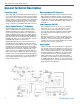
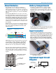
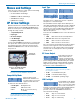
Battery Compartments
The battery compartments are a rugged, straight-
forward design with a recessed entry that captures
the O-ring on the cap. The spring contact on the cap
maintains solid contact on the battery regardless of its
exact length.
The O-rings should be kept clean and dry, and coated
with petroleum jelly on a regular basis. See page 18 for
more information on preventing corrosion.
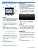
Input Connector
The threaded WP watertight plug on the microphone
cable fits into a recessed jack on the top panel. The re-
cess in the opening retains the O-ring when the plug is
tightened. The Lectrosonics M152WP lavaliere micro-
phone is supplied with the WP plug already installed.
Other microphones can also be terminated with this
plug by following the instructions included with the WP
connector kits.
Treat O-ring with petroleum jelly before
connecting (see page 18)
Equivalent Input Circuit
Diagram
To Virtual Ground
Audio Amplifier
MIC
GND
+5 VDC
Servo Bias
+
To Limiter Control
200 Ohm
100 Ohm
(menu selectable)
Roll-off
332 Ohm
20k
closed for mic level
open for line level
(menu item)
0, 2, 4V
35, 50, 70, 100, 120, 150 Hz
30uF/10V
WM Equivalent
Input Circuit Wiring
About Batteries
The transmitter is powered by two AA batteries.
Lithium batteries are recommended for longest life,
which typically provides over 7.5 hours of operation at
room temperature with the output set to 250 mW. At 50
mW, the runtime is typically over 14 hours with lithium
batteries.
Rechargeable NiMH batteries can also be used, but
the capacity diminishes over time with each successive
recharging cycle. Test the batteries by fully charging
them and then running them down in the transmitter to
determine the available running time. Most Lectroson-
ics receivers have a timer function that will automati-
cally stop when the transmitter shuts down at the end
of battery life, so you will be able to accurately see the
time available.
Alkaline batteries can also be used, but the runtime is
shorter at the full output power. The available runtime
also varies significantly with different brands of AA
alkaline batteries.
Note: Standard zinc-carbon batteries marked
“heavy-duty” or “long-lasting” are not
adequate.
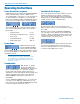
1.6
1.4
1.2
1.0
.8
2468
Hours
Voltage
Varies
Green Red Blink
PWR LED glows green when the battery is good. The
color changes to red at a mid-point of operating life,
and will continue to glow red until the battery gets
close to the end of its life. When the LED begins to
blink red, there are only a few minutes remaining.
The exact point at which the LED turns red will vary
with battery brand and condition, temperature and cur-
rent drain. The LED is simply a reminder intended to
catch your attention, not an exact indicator of remain-
ing time.
•
•
•
•
•
DO NOT COVER
VENT HOLES
Battery polarity is marked
on the rear cover
Unscrew battery caps to
insert batteries
Do not cover
vent holes