
User's Manual


WM, WM/E01, WM/E02, WM/X
LECTROSONICS, INC.
6
LCD Screen
The display is a highly visible, backlit LCD with screens
for making all setup and level adjustments. The trans-
mitter can be powered up with or without the RF output
turned on. With the RF output turned off, all adjust-
ments can be made without creating interference for
other wireless systems in the vicinity.
For normal powering up and down, a countdown ap-
pears in the LCD. The buttons must be pressed for
the duration of the countdown, which helps to prevent
accidentally turning the transmitter on or off.
Power LED
The PWR LED glows green when the battery is good.
The color changes to red when there is about 30
minutes of operation left with the recommended lithium
battery. When the LED begins to blink red, there are
only a few minutes of life.
Note: A NiMH rechargeable battery will give little
or no warning when it is depleted. If you wish
to use NiMH batteries, we recommend trying
fully charged batteries in the unit and using the
battery timer feature available in most receivers
to determine the available operating time.
A weak battery will sometimes cause the PWR LED
to glow green immediately after the unit is turned on,
but will soon discharge to the point where the LED will
turn red or the unit will turn off completely. When the
transmitter is in SLEEP mode, the LED blinks green
every few seconds.
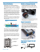
Audio Input Jack
This is a threaded locking connector that accepts the
Lectrosonics watertight WP connector.
Battery Compartment and Thumb Screw
The large knurled thumbscrews are retain the batteries
and maintain solid battery contact. The lanyard keeps
the battery caps attached, but it can be removed if
desired using a 1/16 inch hex key (Allen wrench).
Modulation LEDs
Proper input gain adjustment is critical to ensure the
best audio quality. Two red/green LEDs will glow to ac-
curately indicate modulation levels. The input circuitry
includes a wide range DSP-controlled limiter to prevent
distortion during high peak levels.
It is important to set the gain (audio level) high enough
to achieve full modulation during louder peaks in the
audio. The DSP-controlled limiter can handle peaks
over 30 dB above full modulation, so with an optimum
setting, the LEDs will flash red during use. If the LEDs
never flash red, the gain is too low. The -20 LED turns
red at 0 dB (full modulation).
Signal Level -20 LED -10 LED
Less than -20 dB Off Off
-20 dB to -10 dB Green Off
-10 dB to +0 dB Green Green
+0 dB to +10 dB Red Green
Greater than +10 db Red Red
AUDIO Button
The AUDIO button is used to display the gain and low
frequency roll-off settings. The UP and DOWN arrows
adjust the values. This button is also used with the
FREQ button to enter standby mode and to power the
transmitter on or off.
FREQ Button
The FREQ Button displays the selected operating fre-
quency and also toggles the LCD between displaying
the actual operating frequency in MHz and a two-digit
hexadecimal number that corresponds to the equiva-
lent Lectrosonics Frequency Switch Setting. This but-
ton is also used with the AUDIO button to enter standby
mode and to power the transmitter on or off.
Up/Down Arrows
The Up and Down arrow buttons are used to select the
values on the various setup screens and to lock out
the control panel. Pressing both arrows simultaneously
enters the lock countdown. When an attempt is made
to change a setting while the control panel is locked,
a message will flash on the LCD as a reminder that
the unit is locked. Once locked, the buttons can only
be unlocked by removing the batteries, or with the RM
remote control.
Antenna
The fixed whip antenna is constructed with a flexible,
woven, galvanized steel mesh cable.
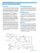
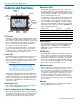
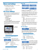
Controls and Functions
Battery
Compartment
Caps
Audio
Input Jack
AUDIO
Button
LCD
FREQ
Button
Modulation
LEDs
PWR LED
UP Arrow
DOWN Arrow