VS1 VIDEO SWITCHER INTERFACE OPERATING INSTRUCTIONS and trouble-shooting guide LECTROSONICS, INC.
INTRODUCTION The VS1 Video Switcher Interface is a microprocessor-based controller used between an automatic microphone mixer and a video switcher. The VS1 provides sophisticated capabilities to synchronize video recording (with up to 8 video cameras) to the audio being recorded, using the logic output capability of an automatic mixer. Typical applications for the VS1 are in audio/video teleconferencing, courtroom video recording, and security applications.
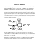
THEORY OF OPERATION The general operation of the VS1 will be described in this section, while the specifics of each programmable option will be outlined in the Operating Instructions. A Motorola MC68HC705 microcontroller is the heart of the VS1. The MC68HC705 controls both the switching relationships between the logic inputs and logic outputs, as well as all user interface functions. Since the MC68HC705 is so highly integrated, parts count is kept to a minimum in the VS1, resulting in higher reliability.
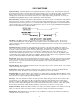
VS1 FUNCTIONS Input Time Delay - Input Time Delay may be adjusted between 0.1 and 10 seconds. This parameter represents the delay between activity on any VS1 logic input and the activation of the associated logic output. The Input Time Delay is factory preset for 2 seconds, but may be adjusted as appropriate to insure that inadvertent camera switching does not take place from transient sounds such as coughs, paper rustling, and the like.
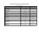
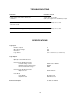
VS1 Function Summary and Default Settings (Version 1.2 firmware) Feature / Function Range Factory Default Input Time Delay Outputs 1 thru 8: 0.1 to 10.0 2.0 Hold Time Delay Outputs 1 thru 8: 0.1 to 25.0 7.0 Hold / Overview Hold Rotate / Overview / Multiple Rotate 0.1 to 10.0 1.
FRONT PANEL DESCRIPTION SELECT PUSHBUTTON - Selects the area on the LCD display for which the Up and Down pushbuttons are active. The blinking cursor will be placed in the selected area. The first line of the display is the name of the selected function. The second line of the display shows the selected channel, and also the current value of the selected function. UP and DOWN PUSHBUTTONS - Allows the VS1 to be cycled through its function options, as well as enabling the function values to be changed.
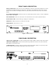
INSTALLATION The VS1 has eight logic inputs, eight logic outputs, and a video synchronization input. The logic inputs provide the interface to an automatic microphone mixer (or other device that generates logic output signals). The logic inputs will accept a switch or relay contact closure or a saturated transistor (eg. an optically isolated LED-Phototransistor combination). The video synchronization input accepts a gen-lock signal from a master timebase and strips the vertical retrace pulse.
SETUP PROCEDURE After the VS1 is installed as outlined in the Installation section (page 6) adjustments may be made to optimize the performance. The VS1 is shipped from the factory with all parameters preset. These presets provide a reasonable starting point from which to further optimize the VS1.
5. Set the IDLE option to either HOLD or OVERVIEW. The Hold setting will keep the last active output on, while the Overview setting will switch to the overview output when no logic inputs are active. 6. Set the SIMULTANEOUS INPUT option to ROTATE, MULTIPLE, or OVERVIEW. The Rotate setting will rotate through all active outputs at a rate determined by the Rotate Time parameter. The Multiple setting will activate the first two active logic inputs.
TROUBLESHOOTING SYMPTOM POSSIBLE CAUSE 1) Video image "rolls" when cameras are switched. 1) Auto Sync set to "Off" 2) No sync signal at the 75 Ohm Sync Input 2) Cameras switch on noise or other transient sounds. 1) Input Time Delay set too short 3) Cameras switch during pauses in speech. 1) Hold Time Delay set too short SPECIFICATIONS Logic Input: Number of Inputs: Open Circuit Voltage: Resistance: Logic Status: 8 +5V 10K Low = channel on (i.e.
SERVICE AND REPAIR If your system malfunctions, you should attempt to correct or isolate the trouble before concluding that the equipment needs repair. Make sure you have followed the setup procedure and operating instructions. Check out the inter-connecting cords and then go through the TROUBLE SHOOTING section in the manual We strongly recommend that you do not try to repair the equipment yourself and do not have the local repair shop attempt anything other than the simplest repair.
LIMITED ONE YEAR WARRANTY The equipment is warranted for one year from date of purchase against defects in materials or workmanship provided it was purchased from an authorized dealer. This warranty does not cover equipment which has been abused or damaged by careless handling or shipping. This warranty does not apply to used or demonstrator equipment. Should any defect develop, we will, at our option, repair or replace any defective parts without charge for either parts or labor.